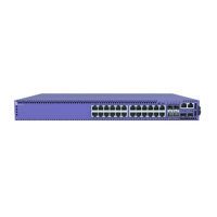
Working carefully, one port at a time, do the following:
1. Verify that you have identied the correct cable for the port.
2. Use an alcohol wipe or other appropriate cleaning agent to clean the cable
connectors; make sure they are free of dust, oil, and other contaminants.
3. If you are using optical ber cable, align the transmit (Tx) and receive (Rx) connectors
with the correct corresponding connectors on the switch or the I/O module.
4. Press the cable connectors into their mating connectors on the switch or I/O module
until the cable connector is rmly seated.
5. Repeat the preceding steps for the remaining cables on this or other switches or I/O
modules.
6. Dress and secure the cable bundle to provide appropriate strain relief and protection
against bends and kinks.
Turn on the Switch
An AC power cord is not included with the AC power supply. You can purchase AC
power cords for use in the US and Canada from Extreme Networks or from your local
supplier. The cord must meet the requirements listed in Power Cord Requirements for
AC-Powered Switches and AC Power Supplies on page 110.
To turn on an Extreme Networks switch, do the following.
1. For switches that are connected to AC power, connect the power cord to the AC
power input socket on the switch (or power supply) and to an AC power outlet.
2. For switches that are connected to DC power, do the following:
a. Verify that the DC circuit is de-energized.
b. Verify that the ground wire is connected to the grounding lug on the rear of the
switch.
The grounding lug is identied by the international symbol for earth ground:
c. Verify that the DC power input cables are properly connected to the DC power
supplies at the rear of the switch.
d. Energize the circuit.
3. When power is connected, verify that the PSU LED turns green.
When the PSU LED has turned green, follow the instructions in Connect Network
Interface Cables on page 77.
If the PSU and RPS LEDs do not turn green, refer to the
LEDs
topic for your switch
model (in 5520 Series Switch LEDs) for troubleshooting information.
Turn on the Switch Installing Your Switch
78 ExtremeSwitching 5420 Series Hardware Installation Guide

 Loading...


