• 1 Serial console port (RJ-45)
• 1 10/100/1000BASE-T out-of-band management port
• 2 USB Type-A ports for management or external ash
• 1 USB Micro-B console port
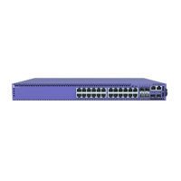
Figure 11: 5420F-16W-32P-4XE Front Panel
1 = 10/100/1000BASE-T ports
(Type 4 PoE (90W))
4 = USB Micro-B console port 7 = USB Type-A
ports
2 = 10/100/1000BASE-T ports
(Type 2 PoE (30W))
5 = 10/100/1000BASE-T out-of-
band management port
8 = SFP-DD
stacking ports
3 = Mode button 6 = RJ-45 serial console port 9 = 1/10G SFP+ ports
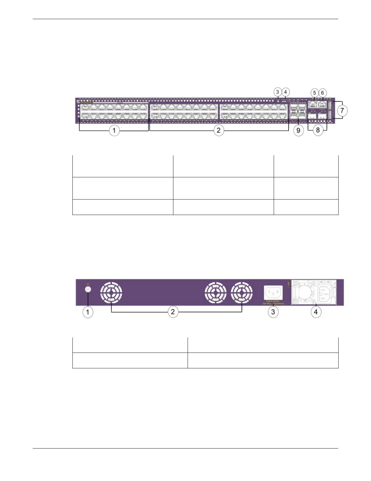
The rear panel of the switch includes:
• 3 xed fan modules
• Grounding lug
• 1 AC power inlet connector
• 1 power supply slot
Figure 12: 5420F-16W-32P-4XE Rear Panel
1 = Grounding lug
3 = AC power inlet connector
2 = Fixed fan modules 4 = Power supply slot
5420F-16W-32P-4XE Switch Features ExtremeSwitching 5420 Series Overview
22 ExtremeSwitching 5420 Series Hardware Installation Guide
 Loading...

