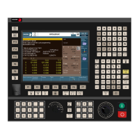
Installation manual
CNC 8060
CNC 8065
CONCEPTS.
9.
(REF: 1402)
·515·
Management of several keyboards.
keys associated with them will be ignored. The relationship between these parameters and
the user keys is the following.
The meaning of this parameter is similar to that of machine parameter JOGKEYBDkbDEF.
To define the behavior of each key, assign to them one of the following values:
• They are defined with a value between 1 and 16 (signed) for the keys that define the axis
and the direction. The sign indicates the positive direction (+) or the negative direction
(-) and the number corresponds to the logic axis, according to parameter AXISNAME.
• They are defined with a value between 1 and 16 (unsigned) for the keys that only define
the axis.
• They are defined with the "+" and "-" values for the keys that only define the moving
direction.
• They are defined with the "R" value for the rapid key.
The user keys defined this way behave like the jog keys whether they've been defined signed
or unsigned and also respect the setting of machine parameter JOGTYPE.
Check the status of the keys.
Registers KEYBD1 y KEYBD2 are a copy of the map of the keys pressed on the last keyboard
used. These registers indicate which key has been pressed (bit=1). If there is only one
keyboard, these registers coincide with KEYBD1_1 and KEYBD2_1. When there are several
keyboards, the contents of these registers are not always the same as KEYBD1_1 and
KEYBD2_1; therefore, they may be used indistinctively.
Registers KEYBD1_n and KEYBD2_n indicate (bit=1) which key has been pressed on each
operator panel. Registers KEYBD1_1 and KEYBD2_1 correspond to the first jog panel,
KEYBD1_2 and KEYBD2_2 to the second one and so on.
Disable the keys.
Registers KEYDIS1, KEYDIS2 and KEYDIS3 inhibit (bit=1) the keys and the switches on all
operator panels at the same time.
Registers KEYDIS1_n, KEYDIS2_n and KEYDIS3_n inhibit (bit=1) the keys and the
switches on each operator panel. Registers KEYDIS1_1 to KEYDIS3_1 correspond to the
first jog panel, KEYDIS1_2 to KEYDIS3_2 to the second one and so on.
When selecting one of the inhibited positions of the feedrate override, the CNC will take the
value of the lowest position allowed. If all of them are inhibited, it will take the value of 0%.
Hardware module. User keys.
JOG-PANEL
PLC marks and registers. Meaning.
KEYBD1 / KEYBD2 These registers are a copy of the map of the keys pressed on the
last keyboard used.
KEYBD1_1 / KEYBD2_1
··
KEYBD1_8 / KEYBD2_8
These registers indicate (bit=1) which key has been pressed on each
operator panel.
PLC marks and registers. Meaning.
KEYDIS1 to KEYDIS3 These registers inhibit (bit=1) the keys and the switches on all
operator panels at the same time.
KEYDIS1_1 to KEYDIS3_1
··
KEYDIS1_8 to KEYDIS3_8
These registers inhibit (bit=1) the keys and the switches on each
operator panel.

 Loading...