FARO
®
Laser Scanner Focus
3D
X 130 Manual
January 2014
23
Chapter 4: Parts and their Functions
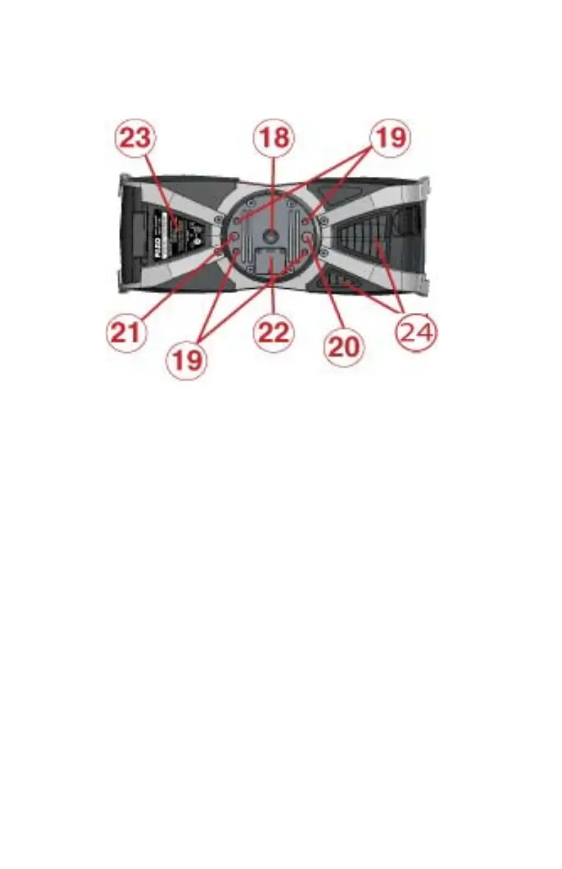
Bottom
3/8” screw thread to mount the scanner to standard photo tripods.
M5 screw threads to mount the scanner to customer specific fixtures.
Pin hole (diameter 8 mm) for scanner adjustment.
Pin hole (diameter 6 mm) for scanner adjustment.
Cover of the automation interface for automated applications. Remove to get
access to the automation interface of the Focus
3D
X 130. For more information,
please read the Focus
3D
X 130 automation interface manual. Cover the
automation interface if it is not needed or not in use.
Type label
Cooling fan openings - please keep these openings uncovered to ensure proper
cooling of the scanner.
For a detailed sketch of the scanner mount, see “Focus
3D
X 130 Mount
Dimensions” on page 116.
Figure 4-5 Bottom View of the Focus
3D
X 130