3.12
hD8625 8-
5
/
8
” 35K Tong
Technical Manual
Assembly Procedures
1. Positionthetongbodygearcaseonasuitablestationarysupport,ensuringthatthebottombodyplateremainsaccessible.
2. Slideasupportrollershaftspacer(PN1037-C-134)intoeachsupportroller(PN1037-135)(totalof12).
3. Presssupportrollerbearings(PN02-0094)intoeachsideofthesupportrollers.Assemblefivesupportrollerassembliesasshown
onPp.5.4-5.5.
4. Installfivesupportrollerassembliesalongonesideofthebodycase.Insertshaftsthroughassemblies,butdonotinstallthebottom
nylocknutsor,whereused,thetopwashers.
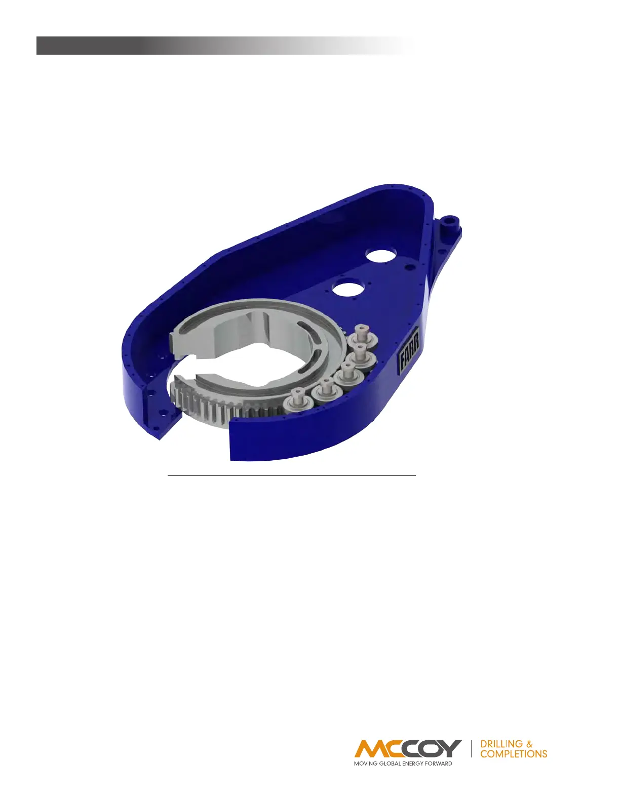
5. Installrotarygear,makingsurethebackingpinslotsareonthesidefacingup.Ensureonesideissupportedbythesupportrollers
installedinStep4,andhavetheopeningintherotarygearorientedasshowninthefollowingillustration.
IllustratIon 3.H.1: tong assemBly - rotary gear InstallatIon
6. Installsupportrollerassembliesinthelocationsexposedbytheopeningintherotarygear.Continuetorotatetherotarygear,install-
ingsupportrollerassembliesintherotarygearopeningasitisrotated.Finishwiththerotarygearalignedwiththeopeninginthe
bottomplateandcompletelysupportedbythesupportrollers.Donotinstallthedoorpivotsupportrollerassemblyatthistime.
7. Presspinionbearing(PN1234-08-01B)intobottompinionbearingcap(PN1050-89),andinstallbearingcapintobottomplateof
tongusingfour1/2”NCx1-1/2”hexboltsand1/2”lockwashers.
8. Presslowerclutchbearing(PN02-0014)intoclutchbearingcap(PN101-0120),andinstallbearingcapintobottomplateoftong
usingfour3/8”NCx1-1/2”hexboltsand3/8”lockwashers.
9. Installaretainerclip(PN02-0009)intobothrotaryidlergears(PN997-A2-119C).Pressanidlerbearing(PN02-0075)intoeachgear
andsecurewithasecondretainerclip.
10. Lightlygreasethelargercircumferenceofthetworotaryidlershafts(PN1050-D5-117)andslidethemthroughthebearingandgears
assemblies,centeringthegearontheshaft.
11. Slidetwobearingseals(PN02-0010)overeachendoftheidlershaftsandpressagainsttheretainerclips(seePp.5.6-5.7for
correctorientation).
12. Slideabearingspacer(PN1050-D5-121)overeachendoftherotaryidlershafts.
13. Placeeach rotaryidlerassemblythroughthebottomplate,ensuring theendsoftheshaftswiththethreadedholeforthegrease
fittingarepointedupwardandtherotaryidlergearsmeshwiththerotarygear.
14. Placeanidlerpad(PN997-D20-125)overthebottomsideofeachrotaryidlershaft,andsecureeachwitha1-1/2”UNFnylocknut.
15. Thelowpiniongear(PN997-A5-88)ismachinedwithshouldersaroundthecentresplineonbothsidesofthegear.Placetheside
ofthelowpiniongearwiththesmallershoulderoverthelowerbearingandbearingcap,centeringasbestasable.
MainTenance