3.18
hD8625 8-
5
/
8
” 35K Tong
Technical Manual
Assembly Procedures (continued...):
48. Inserttwocageplatespacers(PN1050-C3-38)betweenthecageplatesatthefrontofthecageplatesnexttotherotarygear.Secure
thecageplatesthroughthespacersusing1/2”UNCx7-1/2”hexbolts,1/2”narrowflatwashers(onthebottom)and1/2”UNCnylock
nuts.
49. Slidea1/2”flatwasherontoa1/2”UNCx9-1/2”hexbolt,followedbythebackingpinspacer(PN101-4186).Slidethelargerdiam-
eterholeinthebackingpinretainerlink(PN101-4187)evertheendofthe9-1/2”hexboltontothebackingpinspacer.
50. Coathalfofthethreadedconnectingstud(PN101-4097)withblueLoctiteandscrewintothebackingpin(PN101-4188).
51. Inserttheexposedhalfofthethreadeddowelpinthroughthesmallerdiameterholeofthebackingpinretainerlink.Slidethesmall
backingpinspacer(PN101-4096)overthethreadeddowelagainstthebackingpinretainerlink.
52. Positiontheremainingcageplatespacer(PN1050-C3-38)betweenthecageplatesattherearoftheopening.Inserttheboltofthe
backingpinassemblythroughthecageplatesandcageplatespacer,andthebackingpinintooneofthebackingpinholesatthe
rearofthetopcageplate.Securetheboltwitha1/2”narrowwasheranda1/2”UNCnylocknut.
53. Threadthereardoorcylindermountinglug(PN1050-12-001)intothetopplatenexttotheLHtopbrakebandlugweldment(see
illustration3.H.3).
54. Installthedoorpivot shoulder bushings (PN 101-0110)inthedoorweldmentassembly (PN 1050-C4-10) (see Pp.5.28-5.29for
correctbushingorientation).
55. Ifnotalreadydone,installtheremainingsupportrollerassemblylesstheshaftandfastenersbetweenthebodyplatesinthedoor
pivotlocation.
56. Alignthepivotholesinthedoorweldmentwiththepivotholesinthetopandbottomplates.Slidea1-1/8”narrowflatwasheronto
thedoorpivotrollershaft(PN101-3940)andinserttheshaftthroughthedoorbushings,supportrollercomponents,andbodyplates.
Oncetheshaftisfullyinserted(itmayneedtobelightlytapped)securewitha1”narrowflatwasherand1”UNSthinnylocknut.
57. Threada1/2”UNChexnutontoa1/2”UNCx1-3/4”hexbolt.Threadthehexboltintothethreadedholeonthefrontofthedoor
weldment.
58. RefertoPp.5.28-5.29foradoorassemblyillustration.Lightlygreasethedoorlatchadjustmentcam(PN1037-A-14).Positionthe
doorlatchweldment(PN1050-15)atthefrontofthedoorweldment,andinsertthetwolatchsprings(PN997-16)betweenthelatch
weldmentandthedoorweldment.Pressthelatchweldmentagainstthedoorweldmentuntilthelatchpivotholesalign,andinsert
thedoorlatchcamshaft.Securethelatchadjustmentcamtothetopplateofthedoorweldmentwitha3/8”UNCx3/4”hexboltand
3/8”lockwasher.
59. Installmechanicaldoorstop(PN101-1833)tothebottomplateofthetongnexttotheLHbrakebandretainerweldment.Securewith
two3/8”NCx2”boltsand3/8”lockwashers.
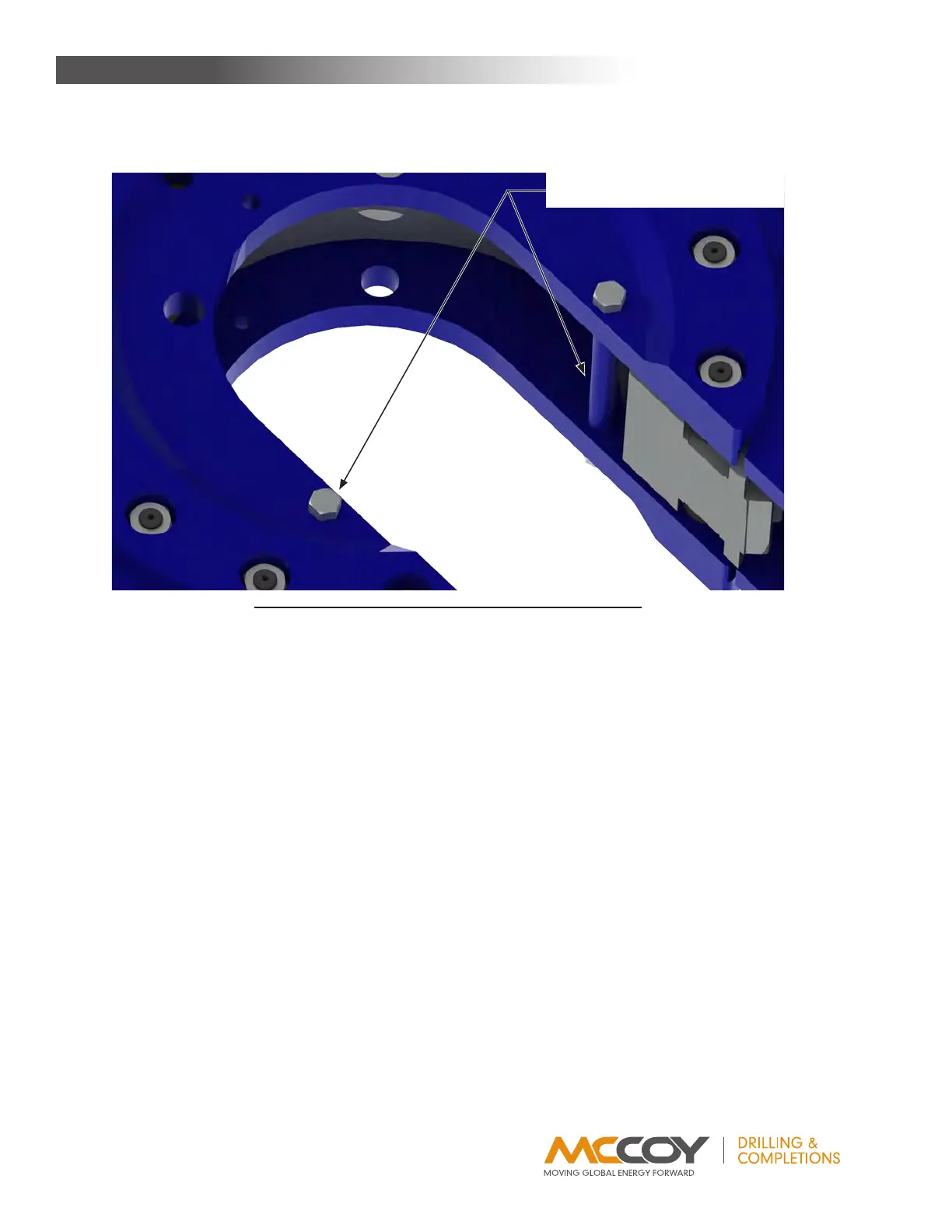
IllustratIon 3.H.8: tong assemBly - front Cage Plate sPaCers
MainTenance
Cage plate spacers & 1/2” NC x
7-1/2” bolt and nut sets