3.20
hD8625 8-
5
/
8
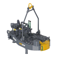
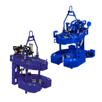
” 35K Tong
Technical Manual
Assembly Procedures (continued...):
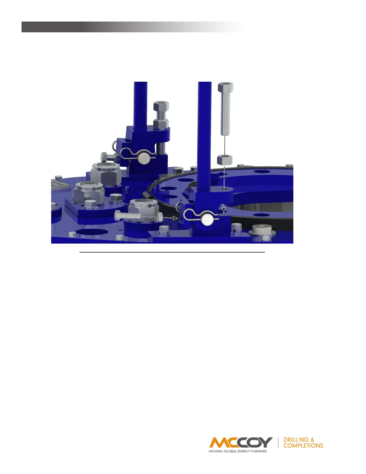
66. Threada3/4”UNChexnutontoeachoftworigidslinglevelingadjustmentweldments(PN1053-C-1L).Threadthelevelingadjust-
mentweldmentsintothefrontoftherigidslingweldmentmountingbrackets,roughlyadjustingthemsotherigidslingisapproxi-
matelyperpendiculartothetopplateofthetong(seeillustration3.H.10).
67. Thread1/2”UNChexnutsontotwo1/2”UNCx1-3/4”hexbolts.Threadtheboltsintotherearoftherigidslingweldmentmounting
brackets.(seeillustration3.H.10).
IllustratIon 3.H.10: tong assemBly - rIgID slIng aDjustment Bolt InstallatIon
68. Attachtherearlegweldment(PN997-D8-160A)tothebottomplateofthetongusinga7/8”UNCx1”hexsocketheadcapscrew
andaregular7/8”flatwasher.
69. Installgreasefittings:
a) Installone1/4”straightthreadgreasefitting(PN02-0097)intothetopsideofeachsupportrollershaft,includingthedoorpivot
rollers(12locationstotal).
b) Installone1/4”straightthreadgreasefitting(PN02-0097)intothetopsideofthelatchadjustmentcam.
c) Installone1/8”NPTgreasefitting(PN02-0005)intothetopofeachidlershaftorhalf-shaft(threelocationstotal).
d) Installone1/8”NPTgreasefitting(PN02-0005)intotheendoftheclutchshaft,inthecentreoftheclutchbearingcap.
e) Installtwo1/8”NPT90
o
greasefittings(PN02-0093)ineachpinionbearingcap(fourlocationstotal).
f) Installtwo1/8”NPT90
o
greasefittings(PN02-0093)inclutchbearingcap(twolocationstotal).
g) Installone1/8”NPT90
o
greasefitting(PN02-0093)orone1/8”NPT45
o
greasefitting(PN02-0006)inthetopofthemotor
mount.
h) Installdrive-ingreasefittings(PN02-0012)intotheendsofeachtongcageplatecamfollower(26locationstotal).
i) Installdrive-ingreasefittings(PN02-0012)intotheendsofeachbackupcageplatecamfollower(26locationstotal).
70. Installhydraulicinletsupportbase(PN101-1138)tothetopplatedirectlyadjacenttotheRHrotaryidler,usingtwo3/8”NCx1”hex
boltsand3/8”lockwashers.Attachtheadjustmentplate(PN101-0022)tothesupportbaseusingtwo3/8”NCx1”hexbolts,3/8”
narrowflatwashers,and3/8”UNChexnylocknuts.
71. Attachtheoutletcouplingsupportmountingbase(PN101-0021)tothetopplateontheRHsideofthemotormountusingfour3/8”
UNCx2”hexsocketheadcapscrews.
72. Attachtheoutletcouplingsupportweldment(PN101-0023)totheweldmentmountusingtwo3/8”NCx1”hexboltsand3/8”lock
washers.Attachtheadjustmentplate(PN101-0277)totheoutletsupportweldmentusingfour3/8”NCx1”hexbolts,3/8”narrow
flatwashers,and3/8”UNChexnylocknuts.
73. Coatthethreadsofthehydraulicvalvemountingposts(PN101-0116)withLoctiteandthreadintothetopplatejustbehindthebrake
bandoneithersideofthebrakebandretainer.
MainTenance