Technical Manual
hD8625 8-
5
/
8
” 35K Tong
3.17
Assembly Procedures (continued...):
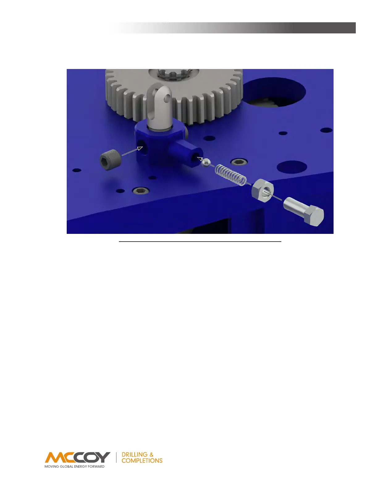
36. Inserttheshifterdetentball(PN02-0018)intothedetenttube,followedbythedetentspring(PN01-0040).Threada7/16”NFhex
jamnutontoa7/16”UNFx1-1/4”hexnut,thenthreadthe7/16”boltintothedetenttube.Thisisthedetentforceadjustmentbolt
andlocknut.
37. Inserttwo5/16”x3/4”dowelpins(PN09-0170)intotheun-threadedholesintherearofthetong,behindtheclutchdrivegearon
eithersideofthecutoutinthetopplate.
38. Placemotormount(PN1050-150)ontotopplateoverthedowelpinsinstalledinthepreviousstep,andsecurewithfour1/2”NCx
1-1/2”hexsocketheadcapscrews.
39. Bolttheshifterlugweldment(PN101-0016)ontothetopplatewithfour3/8”NCx1-1/4”hexboltsand3/8”lockwashers.
40. Attachthemotorgear(PN997-A10-149)tothemotorshaft,securingwithtwo3/8”NCx3/8”flatpointhexsocketsetscrews.Donot
neglecttoinstallthe5/16”squarex1-1/2”keybetweenthegearandthemotorshaft..
41. Installthemotor(PN87-0007)ontothemotormount.SecuretheRHsideofthemotortothemotormountwithtwo1/2”NCx1”hex
socketheadcapscrewsand1/2”lockwashers.
42. TheLHsideofthemotorissecuredwithtwo1/2”NCx1-1/4”hexsocketheadcapscrewsand1/2”lockwashers,whichalsosecures
thetorquegaugeholderweldment(PN1500-09-04A).
43. Installshiftinghandle(PN1037-D-20B).Securethehandletotheshiftershaftandshifterpivotlugweldmentwith5/16”x1-1/2clevis
pins.Useahitchpinoneachclevispintoensuretheydonotbecomedislodged.
44. Installthirteencamfollowers(PN02-0107)inthetopcageplate(PN1050-21HT),andsecureeachawith5/8”UNFhexjamnutand
5/8”lockwasher.Onceinstalledthecamfollowerswillrideinthetopgrooveintherotarygear.
45. Installthirteencamfollowers(PN02-0107)inthebottomcageplate(PN1050-22HT),andsecureeachawith5/8”UNFhexjamnut
and5/8”lockwasher.Onceinstalledthecamfollowerswillrideinthebottomgrooveintherotarygear.
46. Supportthebottomcageplateassemblyagainstthebottomoftherotarygear,withthecamfollowersinthegrooveinthebottomof
therotarygearandtheopeningofthecageplatealignedwiththeopeninginthetongbody.
47. Placethetopcageplateassemblyonthetopoftherotarygear,withthecamfollowersinthegrooveinthetopoftherotarygearand
theopeningofthecageplatealignedwiththeopeninginthetongbody.
IllustratIon 3.H.7: tong assemBly - toP sHIfter BusHIng assemBly
MainTenance