Technical Manual
hD8625 8-
5
/
8
” 35K Tong
3.13
Assembly Procedures (continued...):
16. Installpiniongearshaft(PN997-A7-86B)intothesplineofthebottompiniongearandthelowerpinionbearing.
17. Slide2needlebearings(PN02-1404)overeachendoftheclutchshaft(PN997-HT-50),andpressupagainstcentregear.Slide
lowclutchgear(PN997-HT-52)overthebottomendoftheclutchshaft(thebottomendoftheclutchshaftcanbeidentifiedbythe
threadsforthegreasefittingmachinedintotheend)ontothetwoneedlebearings.Ensurethesmallerdiameterofthelowclutch
gearisdirectlyadjacenttothecentregearontheclutchshaft.Placelowerendofclutchshaftintothelowerclutchbearingthathas
beenpre-mountedinthelowerbodyplate.
18. Installshiftingcollar(PN997-HT-62)overthetopoftheclutchshaftandmeshwithlowclutchgearandthecentregearontheclutch
shaft.
19. Slidetheshiftingforkweldment(PN1050-72)overthebottom(threaded)endoftheshiftingshaft(PN1116-71)andsecurewitha
5/8”UNFhexnutand5/8”UNFhexjamnut.Placetheendoftheshiftingshaftinthelowershiftingbushing(weldedtothebottom
plate)andmeshtheshiftingforkwiththeshiftingcollar.
20. Installaretainerclip(PN02-0009)intothepinionidlergear(PN997-A2-119C).Pressanidlerbearing(PN02-0075)intothegear,
andsecurewiththesecondretainerclip.
21. Slidethepinionidlerhalf-shaft(PN1050-D5-105)throughthepinionidlergearassembly.Slidethebearingseal(PN02-0010)over
theendofthehalf-shaft,andsecuretothehalf-shaftwithashaftretainerclip(PN02-0008).
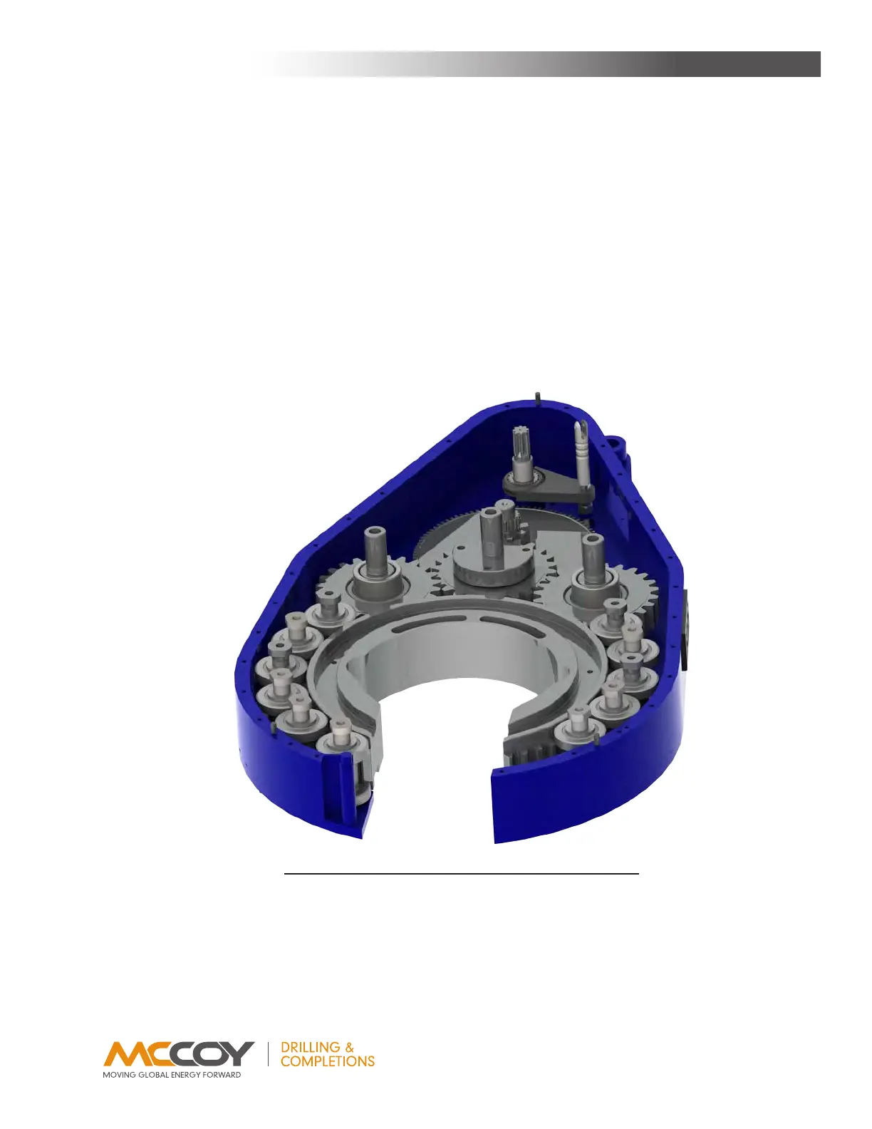
22. Placepinionidlerassemblies,lesstheidlerpadsandtopfasteners,ontopofthelowerpiniongearandplacethemasbestaspos-
sible-theirpositionmayhavetobeadjustedslightlyasthetopplateisattached(seeillustration3.H.2).
IllustratIon 3.H.2: tong assemBly - gear assemBly PosItIonIng
23. Thehigh piniongear(PN997-A4-87B)ismachinedwithshoulders aroundthecentresplineonbothsidesofthegear.Placethe
sideofthehighpiniongearwiththelargershoulderoverthetopofthesplinedpinionshaftandpressagainstthecentregearonthe
pinionshaft.
24. Installhighclutchgear(PN997-HT-51B)ontotheclutchshaft,ensuringthesmallerdiameterisdirectlyadjacenttothecentregear
ontheclutchshaft.
25. Carefullyremoveallsupportrollershafts,usingcautionnottoshiftthepositionoftheinstalledsupportrollerassembliesortodamage
thethreadsontheendoftheshafts.
MainTenance