4-3
1
2
3
4
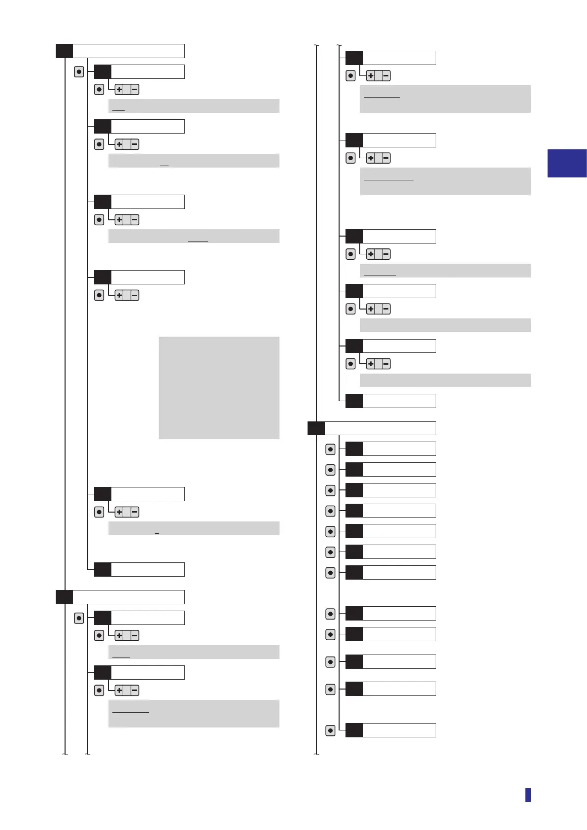
Settings Menu
List of Setting Options
Set count*
D7
OK
OK
1 to 16383 (10)
Detection
*: Displayed when “On” is selected in “D6 Counter”.
Edge direction*
D8
OK
Positive, Negative, Both
*: Displayed when “Edge height” is selected in “D2
Threshold mode”.
*: Displayed when “On” is selected in
“D6 Counter”.
*: Displayed on inter-connection main unit.
Edge hys.*
DA
OK
1 to 9999 (5)
To main menu
DB
I/O polarity
O1
OK
OK
NPN, Push-pull, PNP
I/O
S8
Pin 2 setting
*1
O2
OK
Output 2, Alarm output, Teach input,
Emitter off, Counter reset
*2
, Not used
Serial number
I1
OK
Information
S9
Firmware ver.
I2
OK
Hardware ver.
I3
OK
Temperature
I4
OK
Operation time
I5
OK
Total time
I6
OK
Counter value*
I7
OK
Received light
I8
OK
No. of devices*
I9
OK
*: Displayed on inter-connection main unit and expansion unit.
Device number*
IA
OK
*: Displayed when “Edge height” is selected in
“D2 Threshold mode”.
Edge peak*
IB
OK
To main menu
IC
OK
*: Displayed when “Edge height” is selected in “D2
Threshold mode”.
Edge offset
*1
D9
OK
16 µs: 16 µs to 4080 µs
*2
22 µs: 22 µs to 5610 µs
*3
70 µs: 70 µs to 17850 µs
250 µs: 250 µs to 63750 µs
500 µs: 0.5 ms to 127.5 ms
1 ms: 1 ms to 255 ms
2 ms: 2 ms to 510 ms
8 ms: 8 ms to 2040 ms
This can be set to a value in the following
ranges depending on the [S3] Response
time setting.
*1: Displayed when “Edge height” is selected in “D2
Threshold mode”.
*2: Stand-alone unit and inter-connection main unit with
stand-alone use
*3: Main and expansion units connected
*1: Displayed on 2-outputs and 1-input models.
*2: Displayed when “On” is selected in “D6 Counter”.
*1: Displayed on 1-output and 1-switchable-output/input
models.
*2: Displayed when “On” is selected in “D6 Counter”.
Pin 5 setting*
O3
OK
Output 2, Alarm output, Input ack.,
Not used
*: Displayed on 2-output and 1-input models.
Pin 2 setting
*1
O4
OK
Teach input, Emitter off,
Counter reset
*2
, Load preset, Not used
Lock mode
O5
OK
Lock all, Lock keys
Preset setting
O6
OK
Preset 1 to Preset 5
Load preset
O7
OK
Preset 1 to Preset 5
To main menu
O8
Counter
D6
OK
Off, On
Response
time
Page 4-26
Page 4-26
Page 4-27
Page 4-27
Page 4-28
Page 4-29
Page 4-29
Page 4-29
Page 4-29
Page 4-29
Page 4-29
Page 4-29
Page 4-29
Page 4-29
Page 4-29
Page 4-29
Page 4-29
Page 4-15
Page 4-19
Page 4-21
Page 4-21
Page 4-22
Page 4-22
Page 4-24
Page 4-24
Page 4-25