3 Mechanical installation
Festo – GDCP-CMMP-M0-HW-EN – 1511c – English 19
3 Mechanical installation
3.1 Important notes
Note
Proceed carefully when mounting. During mounting and subsequent operation of the
drive, ensure that that no metal shavings, metal dust or mounting parts (screws, nuts,
pieces of wire) fall into the motor controller.
Note
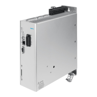
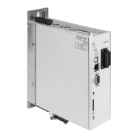
The motor controllers CMMP-AS-...-M0
Use only as installed devices for control cabinet mounting.
Mounting orientation with the power supply [X9] on top.
Mount it with the clip on the mounting plate.
Installation clearances:
For sufficient ventilation of the device, a minimum clearance of 100 mm to other
sub-assemblies is required above and below the device.
An installation clearance of 150 mm underneath the device is recommended for
optimum wiring of the motor or encoder cable!
The motor controllers of the CMMP-AS-...-M0 family are designed in such a way that
they can be mounted directly on a heat-dissipating mounting plate if used as inten
ded and installed correctly. We wish to point out that excessive heating can lead to
premature aging and/or damage to the device. With high thermal stress on the mo
tor controller CMMP-AS-...-M0, a mounting distance (è Fig. 3.2) is recommended!

 Loading...


