4 Electrical installation
Festo – GDCP-CMMP-M0-HW-EN – 1511c – English 25
4.2 Allocation of the plug connectors
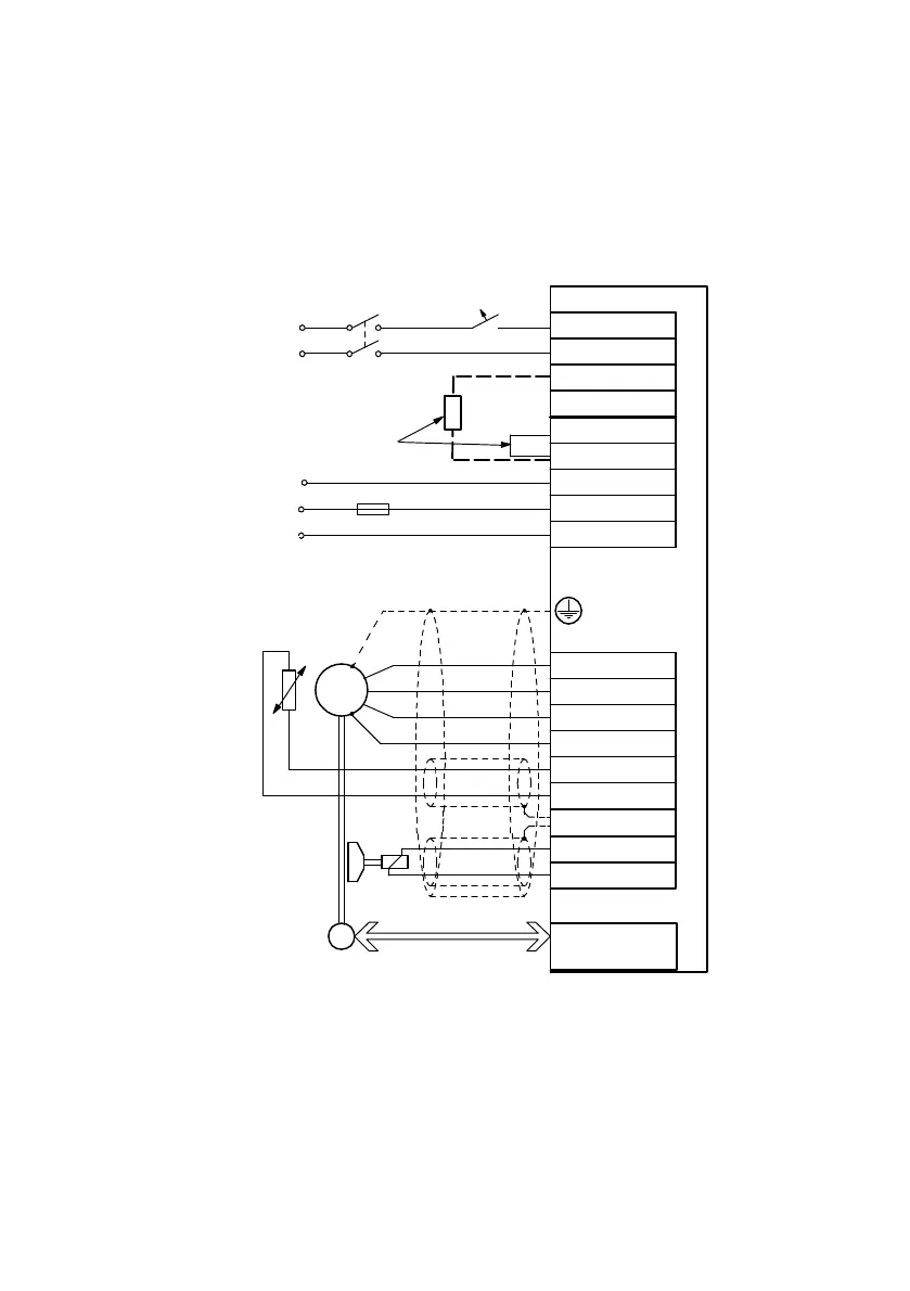
The motor controller CMMP-AS-...-M0 is connected to the supply voltage, the motor, the external brak
ing resistor and the holding brake in accordance with the following circuit diagrams.
0 V
external
Braking resistor
alternative
Encoder/resolver
Angle encoder
PE
BR-CH
BR-INT
ZK+
ZK-
L
N
24V+
GND24V
U
V
W
PE
MT+
MT-
PE
BR+
Br-
E
M
3~
T
X9
X6
X2A/X2B
Single-phase
min. 100 V AC -10 %
max. 230 V AC +10 %
internal
PE
+24 V
Encoder
/Resolver
24 V DC supply
Connection for the outer
screening of the motor cable
L
N
Power circuit
breakers
Fig. 4.1 CMMP-AS-...-3A-M0: Single-phase connection to the supply voltage and the motor
 Loading...


