4 Electrical installation
26 Festo – GDCP-CMMP-M0-HW-EN – 1511c – English
Note
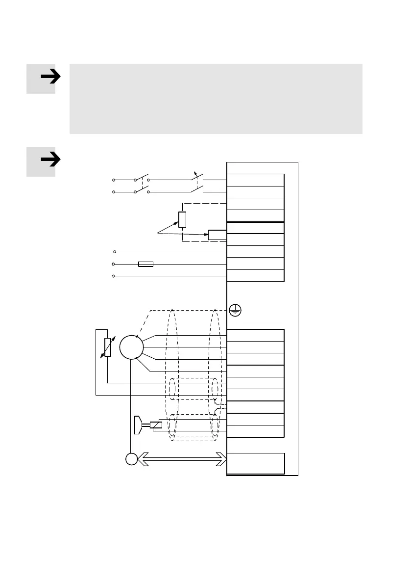
The maximum voltage of 230 V AC +10 % must be present between the external con
ductors è Fig. 4.2.
In typical European low voltage networks that have a nominal star voltage of 230 V, a
mesh voltage of approx. 400 V develops between two external conductors, which could
result in damage to the motor controller!
0 V
external
Braking resistor
alternative
Angle encoder
PE
BR-CH
BR-INT
ZK+
ZK-
L
N
24V+
GND24V
U
V
W
PE
MT+
MT-
PE
BR+
Br-
E
M
3~
T
X9
X6
X2A/X2B
2-phase
min. 100 V AC -10%
max. 230 V AC +10%
internal
PE
+24 V
Encoder/
Resolver
24 V DC supply
Connection for the outer
screening of the motor cable
L1
L2
Power circuit
breakers
Fig. 4.2 CMMP-AS-...-3A-M0: Dual-phase connection L1/L2 to the supply voltage and the motor
 Loading...


