4 Electrical installation
30 Festo – GDCP-CMMP-M0-HW-EN – 1511c – English
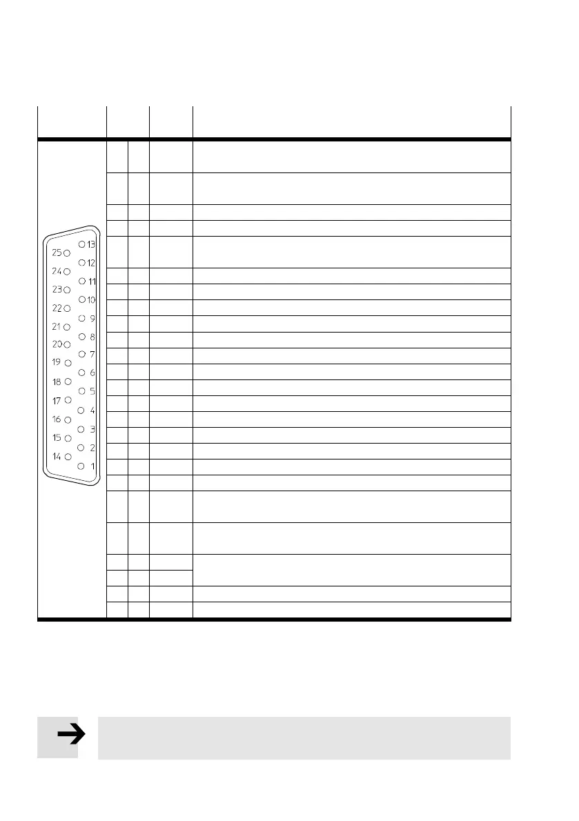
The standard assignment of the I/O interface in the FCT corresponds to è Tab. 4.5.
[X1]
Pin no. Desig
nation
Specification
13 DOUT3 Following error, output freely parameterisable, optionally paramet
erisable as DIN11
25 DOUT2 Brake unlocked, output freely parameterisable, optionally paramet
erisable as DIN10
12 DOUT1 Motion Complete, Output freely parameterisable
24 DOUT0 Controller ready, output permanently assigned
11 DIN 9 Flying measurement (sample)/reference switch, input freely para
meterisable
23 DIN 8 Start positioning task, input freely parameterisable
10 DIN7 Limit switch 1 (blocks n 0), input permanently assigned
22 DIN6 Limit switch 0 (blocks n 0), input permanently assigned
9 DIN5 Controller enable, input permanently assigned
21 DIN4 End stage enable, input permanently assigned
8 DIN 3 Position selector bit 3, input freely parameterisable
20 DIN 2 Position selector bit 2, input freely parameterisable
7 DIN 1 Position selector bit 1, input freely parameterisable
19 DIN 0 Position selector bit 0, input freely parameterisable
6 GND24 Reference potential for digital I/Os
18 +24 V 24 V output
5 AOUT1 Position setpoint value, analogue output freely parameterisable
17 AOUT0 Speed setpoint value, analogue output freely parameterisable
4 +VREF Reference output for setpoint potentiometer
16 AIN13 Setpoint input 2, single ended analogue input, optionally paramet
erisable as DIN13
1)
3 AIN12 Setpoint input 1, single ended analogue input, optionally paramet
erisable as DIN12
1)
15 #AIN0 Setpoint input 0, differential analogue input
2 AIN0
14 AGND Reference potential for analogue signals
1 AGND Screening for analogue signals, AGND
1) Configuration with FCT. Observe not è Section 4.3.3.
Tab. 4.5 Pin assignment: I/O communication [X1] (FCT factory setting)
4.3.3 Use analogue inputs as digital inputs
If the digital inputs AIN1 and ANI2 are used as digital inputs, then a ground reference from AGND to
GND24 at plug X1 pins 14 and 6 must be established.
Note
Connecting AGND to GND24 renders the electronics overvoltage protection inoperable.
 Loading...


