4 Electrical installation
32 Festo – GDCP-CMMP-M0-HW-EN – 1511c – English
4.4 Connection: Resolver [X2A]
4.4.1 Plug [X2A]
Motor controller Design on the device Counterplug
CMMP-AS-...-M0 Sub-D plug connector, 9-pin, socket Sub-D plug connector, 9-pin, pins
Tab. 4.6 Plug design [X2A]
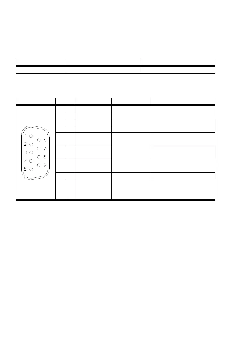
4.4.2 Pin assignment [X2A]
[X2A] Pin no. Designation Value Specification
1 S2 3.5 V
eff
5-10 kHz
R
i
5 kΩ
SINE tracking signal,
differential
6 S4
2 S1 3.5 V
eff
5-10 kHz
R
i
5 kΩ
COSINE tracking signal,
differential
7 S3
3 AGND 0 V Screening for signal pairs
(inner screening)
8 MT- GND Reference potential for
temperature sensor
4 R1 7 V
eff
5-10 kHz
I
A
150 mA
eff
Carrier signal for resolver
9 R2 GND
5 MT+ +3.3 V R
i
= 2 kΩ Temperature sensor, motor
temperature, N/C contact, PTC,
KTY ...
Tab. 4.7 Pin assignment [X2A]
The outer screening must always be connected to the PE (plug housing) of the motor controller.
The inner screenings must be placed on one side on the motor controller CMMP-AS-...-M0 on PIN3 of
[X2A].
 Loading...


