4 Electrical installation
40 Festo – GDCP-CMMP-M0-HW-EN – 1511c – English
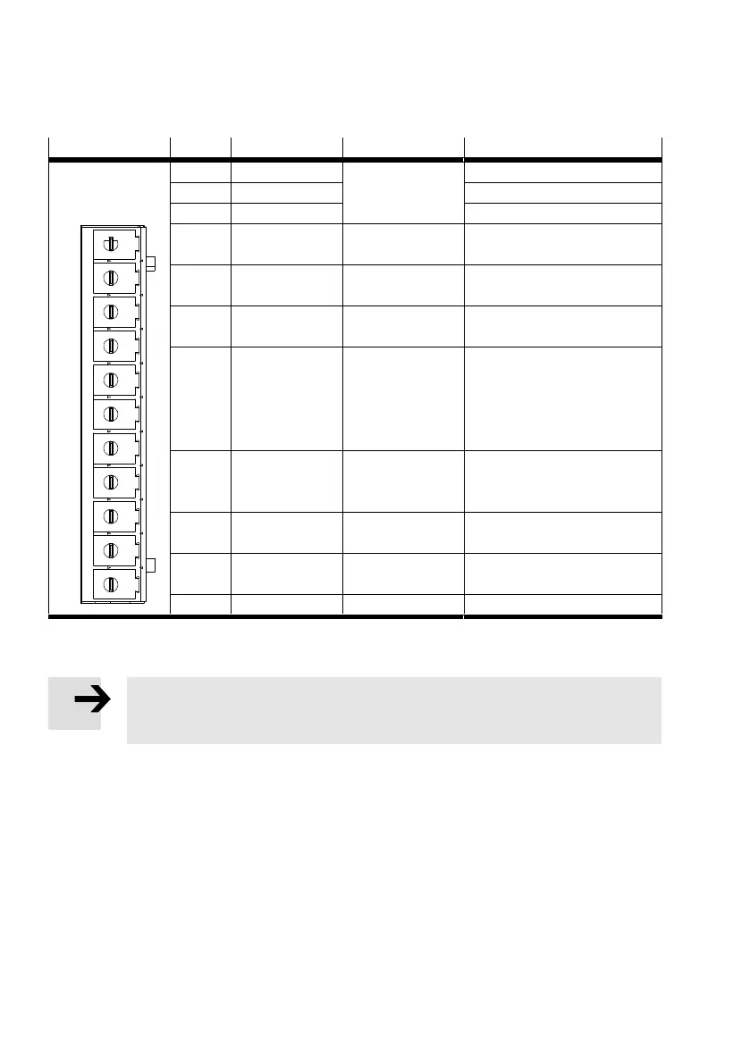
4.8.3 Pin assignment [X9] – triple-phase
[X9]1)
Pin no. Designation Value Specification
1
11
1 L1 230 … 480 V AC
±10%
50 … 60 Hz
Mains phase 1
2 L2 Mains phase 2
3 L3 Mains phase 3
4 ZK+ … 700 V DC Alternative supply: Positive in
termediate circuit voltage
5 ZK- GND_ZK Alternative supply: Negative in
termediate circuit voltage
6 BR-EXT 800 V DC Connection of the external
braking resistor
7 BR-CH 800 V DC Brake chopper connection for
– internal braking resistor
against BR-INT – or –
– external braking resistor
against BR-EXT
8 BR-INT 800 V DC Internal braking resistor connec
tion (bridge after BR-CH with use
of the internal resistor)
9 PE PE Connection for protective con
ductor from the mains
10 +24V +24 V DC ±20 % Supply for control section,
holding brake and I/O
11 GND24 V GND24 V DC Reference potential for supply
1) Representation of the contact strip on the motor controller CMMP-AS-...-11A-P3-M0
Tab. 4.18 Pin assignment [X9] – triple-phase
Note
The DC power supply must be generated from a max. 230/400 V or a max. 277/480 V
grid.
 Loading...


