4 Electrical installation
Festo – GDCP-CMMP-M0-HW-EN – 1511c – English 49
4.12 Connection: I/O interface for STO [X40]
4.12.1 Plug [X40]
Motor controller Design on the device Counterplug
CMMP-AS-...-M0 PHOENIX MINICOMBICON MC
1.5/8-GF-3.81 BK
PHOENIX MINICOMBICON MC
1.5/8-STF-3.81 BK
Tab. 4.24 Plug design [X40]
4.12.2 Pin assignment [X40]
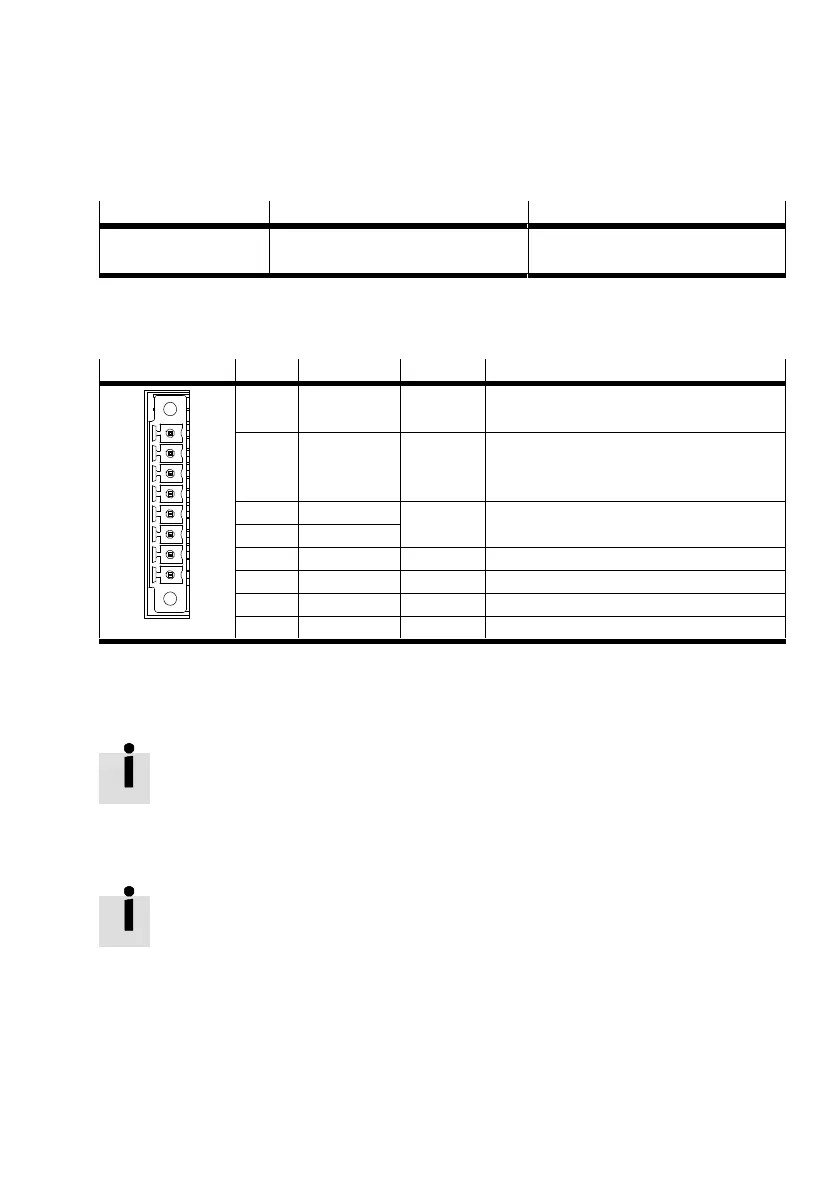
[X40]1) Pin no. Designation Value Specification
8 0 V 0 V Reference potential for auxiliary power
supply.
7 24 V +24 V DC Output for auxiliary power supply (24 V DC
logic supply of the motor controller
brought out).
6 C2 – Feedback contact for the status “STO” on
an external controller.
5 C1
4 0V-B 0V Reference potential for STO-B.
3 STO-B 0 V / 24 V Control port B for the function STO.
2 0V-A 0 V Reference potential for STO-A.
1 STO-A 0V / 24V Control port A for the function STO.
1) Representation of the plug on the device of the motor controller CMMP-AS-...-M0
Tab. 4.25 Pin assignment [X40]: I/O interface for STO
4.12.3 Circuitry with use of the STO safety function [X40]
To work safely with the safety function STO – “Safe Torque Off”, please observe the in
formation in the documentation è GDCP-CMMP-AS-M0-S1-... .
4.12.4 Circuitry without use of the STO safety function [X40]
If you do not need the integrated safety function STO in your application, to operate the
motor controller you must connect the X40 interface, as depicted in Fig. 4.8.
This deactivates the integrated safety function!
When using this circuitry for the CMMP-AS-...-M0, safety in the application must be en
sured through other appropriate measures.
 Loading...


