4 Electrical installation
Festo – GDCP-CMMP-M0-HW-EN – 1511c – English 55
4.13.5 Operation with long motor cables
For applications in combination with long motor cables and/or if the wrong motor cables are selected
with excessive cable capacity, the filters may be subjected to thermal overload. To avoid this, it is ne
cessary to enter the cable length used in the application in the FCT parametrisation software. By using
this information the FCT plug-in then automatically calculates the optimal cycle time for the current
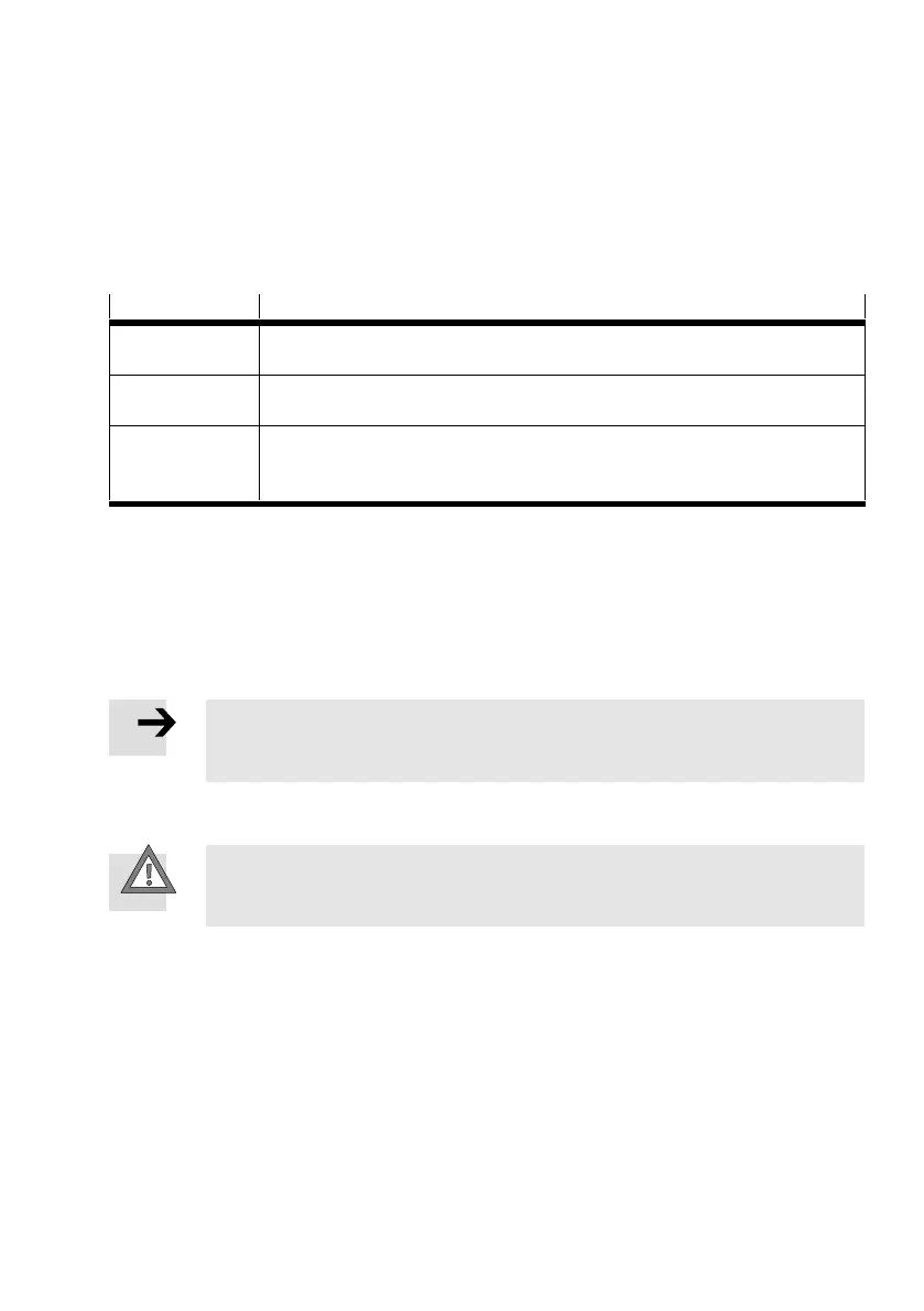
regulator and PWM control. The following restrictions are taken into consideration:
Cable length
Restrictions in the FCT plug-in CMMP
≤ 15 m – The minimum value for “cycle time current regulator” is 62.5 µs.1)
– The option “half output stage frequency” is set and can be edited.2)
, 15 m, ≤ 25 m – The minimum value for “cycle time current regulator” is 62.5 µs.1)
– The option “half output stage frequency” is set and cannot be edited.
, 25 m – The minimum value for “cycle time current regulator” is 125 µs and cannot be
edited.
– The option “half output stage frequency” is set and cannot be edited.
1) The actual value is automatically determined by the FCT based on the motor controller axis combination.
2) The ability to edit the option “half output stage frequency” does not apply to three-phase controllers.
Tab. 4.29 Restrictions in the FCT plug-in depending on the cable length
In addition, the following procedure is strongly recommended for applications in which long motor
cables are required:
– From a cable length of , 25 m, use only cables with a capacitance between the motor phase and
screening of < 200 pF/m, or better, < 150 pF/m and also use a mains filter!
Note
Longer cable lengths result in deviations to the current regulator amplification (line
resistance).
4.13.6 ESD protection
Caution
Unused Sub-D plug connectors present a danger of damage to the device or to other
parts of the system as a result of ESD (electrostatic discharge).
In the design of the motor controller CMMP-AS-...-M0, great importance has been placed on high resist
ance to interference. For this reason, individual function blocks are galvanically separated from each
other. Signal transmission within the device is performed via an optocoupler.
A distinction is made between the following separated areas:
– Output stage with intermediate circuit and mains input
– Control electronics with analogue signal processing
– 24 V supply and digital inputs and outputs
 Loading...


