4 Electrical installation
44 Festo – GDCP-CMMP-M0-HW-EN – 1511c – English
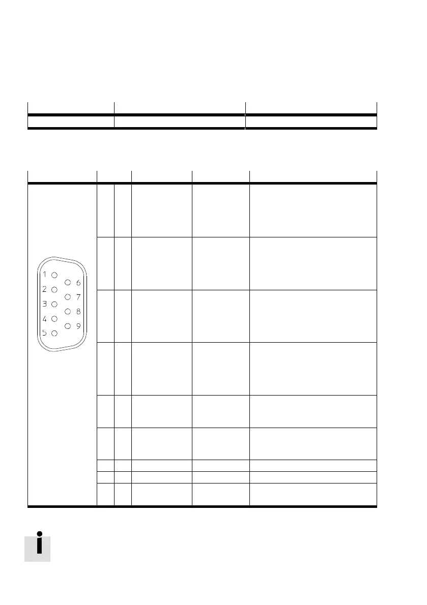
4.9 Connection: Incremental encoder input [X10]
4.9.1 Plug [X10]
Motor controller Design on the device Counterplug
CMMP-AS-...-M0 Sub-D plug connector, 9-pin, socket Sub-D plug connector, 9-pin, pins
Tab. 4.20 Plug design [X10]
4.9.2 Pin assignment [X10]
[X10] Pin no. Designation Value Specification
1 A/CLK/CW 5 V R
I
L 120 Ω Incremental encoder signal A
Stepper motor signal CLK
Pulses clockwise CW
pos. polarity in accordance with
RS422
6 A#/CLK#/CW# 5 V R
I
L 120 Ω Incremental encoder signal A
Step motor signal CLK
Pulses clockwise CW
neg. polarity in accordance with
RS422
2 B/DIR/CCW 5 V R
I
L 120 Ω Incremental encoder signal B
Step motor signal DIR
Pulses counterclockwise CCW
pos. polarity in accordance with
RS422
7 B#/DIR#/CCW# 5 V R
I
L 120 Ω Incremental encoder signal B
Step motor signal DIR
Pulses counterclockwise CCW
neg. polarity in accordance with
RS422
3 N 5 V R
I
L 120 Ω Incremental encoder zero pulse N
pos. polarity in accordance with
RS422
8 N# 5 V R
I
L 120 Ω Incremental encoder zero pulse N
neg. polarity in accordance with
RS422
4 GND – Reference GND for encoder
9 GND – Screening for the connecting cable
5 VCC +5 V ±5%
100 mA
Auxiliary supply, maximum load
100 mA, short-circuit proof!
Tab. 4.21 Pin assignment X10: Incremental encoder input
When connecting two motor controllers in the master-slave mode via [X11] and [X10], the
pins 5 (+5 V - auxiliary supply) must not be connected to each other.
 Loading...


