EasyManuals Logo

Festo CP Series User Manual

Festo CP Series
109 pages
To Next Page IconTo Next Page
To Previous Page IconTo Previous Page
Page #14 background imageLoading...
Page #14 background image
End plate Plate at the left and right-hand ends of the CP terminal with
channels or connections for compressed air supply to the valves
and for the exhaust.
HHB Manual override
I/O Input/output modules
Isolating plate Plate for dividing the valve terminal into two pressure zones
Pneumatic multiple
connector plate
Board for central wiring of the valve terminal
(connections for supply air, exhaust and work air)
Relay plate Plate with relay coils for controlling two electrically isolated outputs
Tubing connections Connection of supply tubing (hoses) to the CP terminal
Valve plate Plate with single or double solenoid valves
Valve block Basic unit with valve, isolating, blanking, relay and end plates
XII CPV.. 9802

Questions and Answers:

Question and Answer IconNeed help?

Do you have a question about the Festo CP Series and is the answer not in the manual?
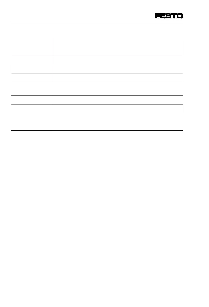
Festo CP Series Specifications

General IconGeneral
TypeController
SeriesCP
CategoryController
ManufacturerFesto
Operating Voltage24 V DC
Protection ClassIP20
Communication InterfaceCANopen, PROFINET
Programming EnvironmentFesto Automation Suite
Number of AxesVaries (depending on model, typically up to 6 or more)

Related product manuals