2.2.2 Fitting the CP terminal onto the pneumatic
multiple connector plate
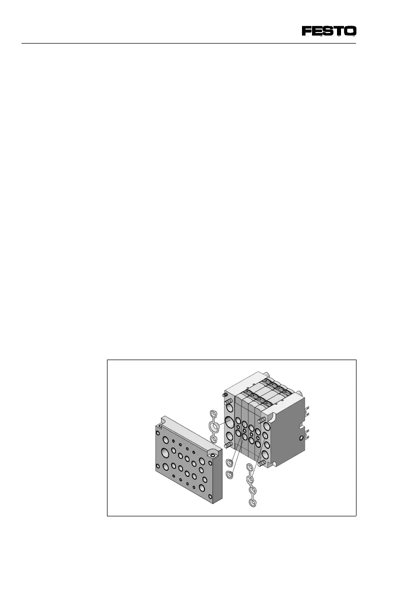
Proceed as follows:
• In the case of CP terminals with individual connec-
tion, insert the socket head screws supplied into the
fastening holes of the CP terminal. In the case of CP
terminals with MP, AS-i or CP connection, the socket
head screws are already inserted with a retaining de-
vice in the fastening holes under the electrical
connector plate.
• Place the 3-seal or 4-seal strips for sealing the sup-
ply channels into the grooves in the left or right-hand
end plate.
• In order to seal the work channels, carefully press
the 2 individual seals into the threads of the work
connections.
• Screw the CP terminal onto the pneumatic multiple
connector plate with the 4 socket head screws. Tigh-
ten the screws in diagonally opposite sequence with
2 Nm (CPV10/14) or 4 Nm (CPV18).
Fig. 2/7: Fitting the CP terminal onto the
pneumatic multiple connector plate
2. Fitting
2-14 CPV... 9802

 Loading...


