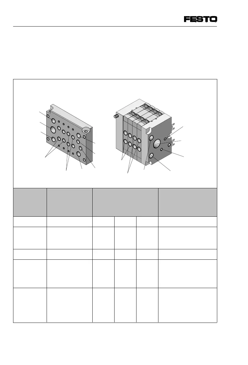
3.2.2 Connecting the supply and work tubing
Fit the screw connectors or silencers as shown in the
table below. Then connect the tubing.
With pneumatic multiple connector plate Without pneumatic multiple connector plate
Connection
code
ISO 5599
Tubing Connection size ISO 228,
Specifications in brackets
for extended pneum.
multiple connector plate
Connection
CPV10 CPC14 CPV18
1 or 11 Compressed air/
vacuum
G 1/8 G 1/4 G 3/8 Screw connector in end
plates or pneumatic
multiple connector plate
2 or 4 Work air/vacuum M7 G 1/8 G 1/4 Screw connector
3/5 Exhaust right/
left-hand end plate
Pneum. multiple
connector plate
G 3/8
G 1/4
G1/2
G3/8
G 1/2
G 1/2
Screw connector
- for ducted exhaust air
- for silencers
12/14
or
82/84
Auxiliary pilot air/
exhaust right/
left-hand end plate
Pneum. multiple
connector plate
M5
M7 (M5)
G 1/8
G 1/8
G 1/4
G 1/4
Screw connector on
connection 82/84
- for ducted exhaust air
- for silencers
Fig. 3/3: Assigning the connections
3/5
3/5
11
4
2
2
4
1
82/84
82/84
1
1
12/14
11
3. Installation
3-8 CPV... 9802

 Loading...


