1.2 Description of components
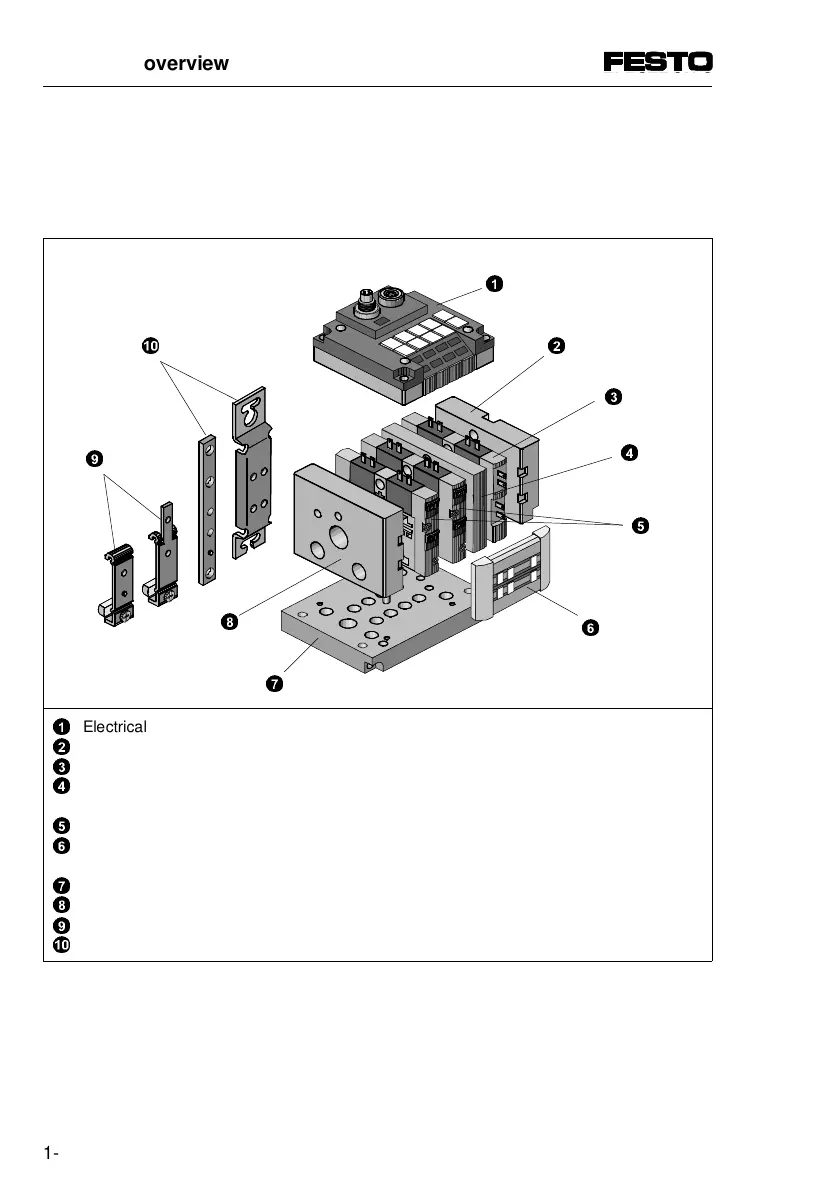
The CP terminal consists of the following components:
1
2
3
4
5
6
7
8
9
0
Electrical connector plate with MP, AS-i or CP connection
Right-hand end plate (with/without supply connections or for pneum. m.c. plate)
Relay plate (only for CPV10/14 terminals with CP connection)
Blanking or isolating plate (with blocked air channels 1 and 11 and
exhaust channel (3/5) or only blocked air channels 1 and 11
Valve plates fitted with single or double solenoid valves
Identifying plate and cover of manual override for inscription clips (optional) not in
connection with relay plate
Pneumatic multiple connector plate (optional)
Left-hand end plate (with/without supply connections or for pneum. m.c. plate)
Support for hat-rail mounting (optional) for CPV10/14 or CPV18
Support for wall fastening (optional) for CPV10/14 or CPV18
Fig. 1/3: Components of the valve terminal
8
2
7
0
9
3
5
1. System overview
1-8 CPV... 9802

 Loading...


