EasyManuals Logo

Festo CP Series User Manual

Festo CP Series
109 pages
To Next Page IconTo Next Page
To Previous Page IconTo Previous Page
Page #73 background imageLoading...
Page #73 background image
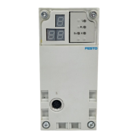
The LEDs show the switching status of the valve sole-
noid coils. The meaning of the LEDs is shown in the
table below.
LED Switching position of valve Meaning
Yellow out Basic position Logic 0 (signal not applied)
Yellow alight Switch position
or
basic position
Logic 1 (signal applied)
Logic 1 but:
operating voltage of outputs is
below permitted tolerance range
(DC 20.4 V to 26.4 V)
or
compressed air supply not correct
or
pilot exhaust blocked
or
return for servicing
4. Commissioning
CPV... 9802 4-13

Questions and Answers:

Question and Answer IconNeed help?

Do you have a question about the Festo CP Series and is the answer not in the manual?

Festo CP Series Specifications

General IconGeneral
TypeController
SeriesCP
CategoryController
ManufacturerFesto
Operating Voltage24 V DC
Protection ClassIP20
Communication InterfaceCANopen, PROFINET
Programming EnvironmentFesto Automation Suite
Number of AxesVaries (depending on model, typically up to 6 or more)

Related product manuals