Releasing Operations System Operation
FCP-75 Manual — P/N:LS10147-003FK-E:A 3/17/2021 109
When a Single or Double Interlock Zone releasing is selected the system will automatically default the FIK-5496 Intelligent Power Module
in the following system parameters:
• Output Group 2 is created. Output Group 2 will be defaulted as an “Alarm” output group for all releasing zones. NAC [01:001] is
assigned to Output Group 2.
• Output Group 3 is created. Output Group 3 will be defaulted as an “Pre-Alert” output group for all releasing zones. NAC [01:002] is
assigned to Output Group 3.
• Output Group 4 is created. Output Group 4 will be defaulted as a “Release” output group for all releasing zones. NAC circuit [01:003]
is assigned to Output Group 4.
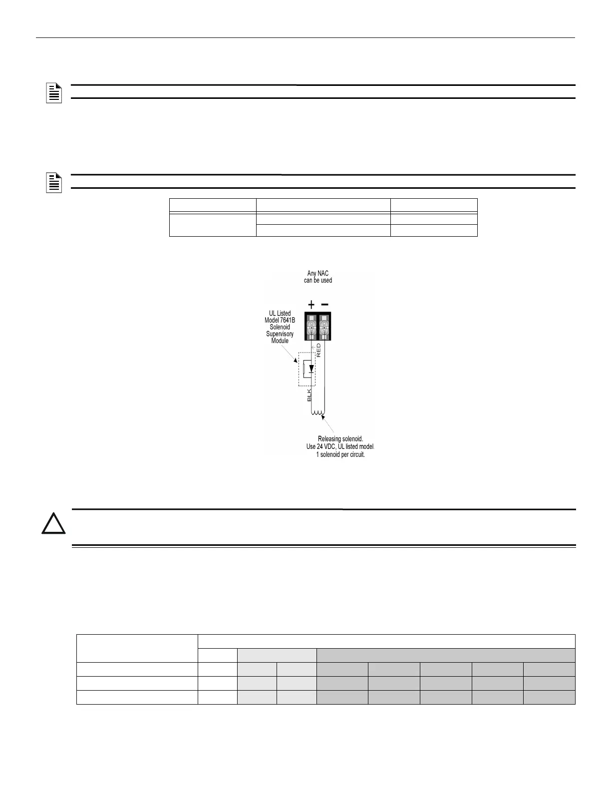
Figure 10.1 Wiring Configuration for Solenoid
10.7.1 Single Interlock Zone Releasing
A single interlock zone utilizes a minimum of two addressable detectors, and a designated manual release switch.
Conditions Required for an Pre-Alert Output Activation
If any single addressable detector is activated, the “Pre-Alert” output will activate and the “Pre-Alarm” output will deactivate. This alerts the
user that the initial stages required for a release condition are present. (Also refer to Table 10.4).
Conditions required for an General Alarm and Release Output Activation
If two or more addressable detectors, or a manual release switch activate, the “Alarm” and the “Release” outputs will activate. (Also refer to
Table 10.4).
NOTE: The defaults created can be modified through programming if desired.
NOTE: The installer must define which input points will be used for detectors, manual release switches, or interlock/pressure switches.
Manufacturer Part Number Rating
Asco T8210A107 24 VDC, 2.5A
8210G207 24 VDC, 2.5A
Table 10.2 Approved Releasing Solenoids
The Model 7641-L8
Must be located
at the solenoid.
*
CAUTION: ADDRESSABLE DETECTORS ONLY
ONLY ADDRESSABLE DETECTORS CAN BE USED. NO CONVENTIONAL DETECTORS CAN BE USED. EACH SINGLE
INTERLOCK ZONE INPUT REQUIRES AT LEAST ONE MANUAL RELEASE SWITCH.
Inputs
Output Results
Normal
Pre-Alert Release and General Alarm
1st Addressable Detector
X X X X
2nd Addressable Detector
X X X X
Manual Release Station
X X X X
Table 10.3 Input Conditions and Output Results