38 FCP-75 Manual — P/N LS10147-003FK-E:A 3/17/2021
Control Panel Installation FIK-5880 LED Driver Module
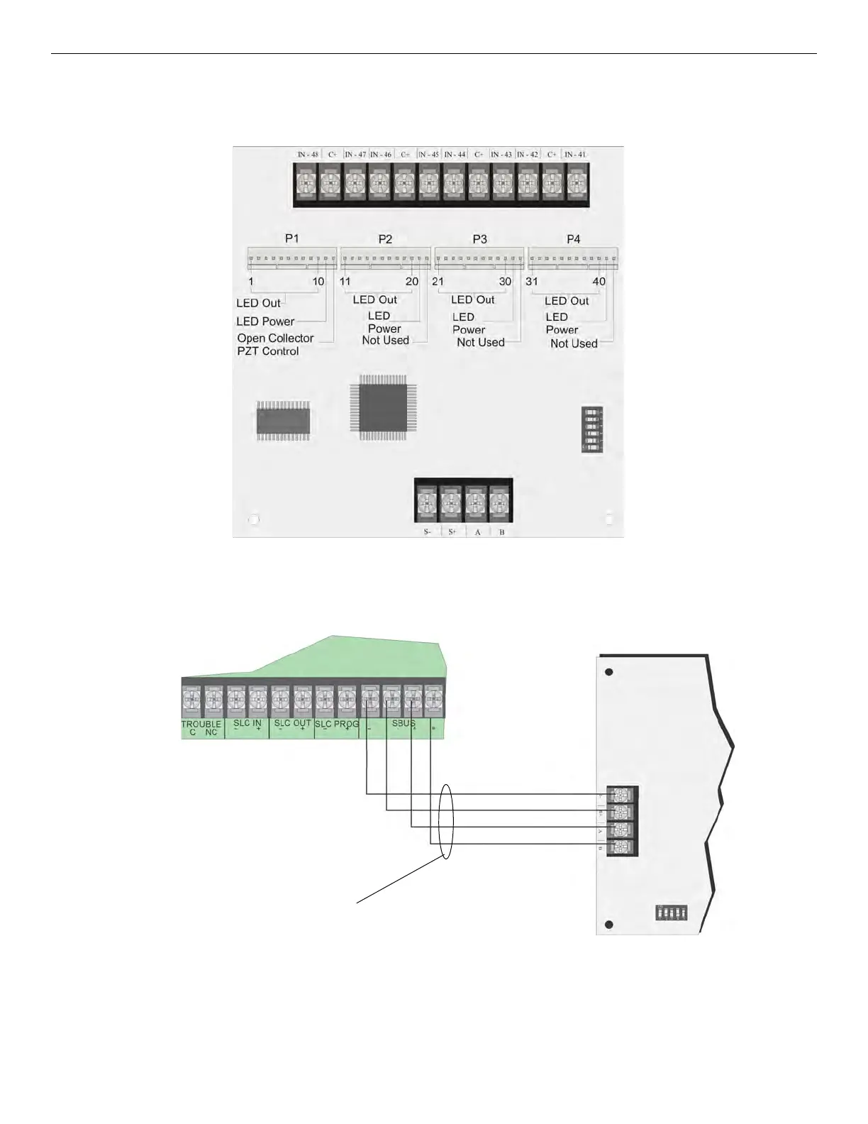
4.9.1 FIK-5880 Board Layout
Figure 4.31 is a picture of the FIK-5880 board showing locations of screw terminals for connection to the panel and contact monitor wiring;
pin connectors for connecting LEDs; and the DIP switch for selecting an SBUS ID number.
Figure 4.31 FIK-5880 Board Layout
4.9.2 FACP Connection
The FIK-5880 connects to the panel via the SBUS. Make connections as shown in Figure 4.32. After the FIK-5880 is connected to the panel,
it must be added to the system. This programming step is described in Section 9.
Figure 4.32 FIK-5880 Connection to Main Control Panel Assembly
4.9.3 LED Wiring
There are four 12-pin connectors on the FIK-5880 board for connecting LEDs. Each LED gets its power from Pin 11. Internal resistors are
sized so that there is approximately 10 mA of current for each LED; no series resistors are required. LED outputs can be mapped to output
circuits. See Section 9 for Programming details.
Wire the LEDs as shown in Figure 4.33.
SBUS Address
DIPs
Dry Contact Inputs - Supervised/power-limited
SBUS Connection