16 FCP-75 Manual — P/N LS10147-003FK-E:A 3/17/2021
Before You Begin Installing Wiring Specifications
3.5 Wiring Specifications
Induced noise (transfer of electrical energy from one wire to another) can interfere with telephone communication or cause false alarms. To
avoid induced noise, follow these guidelines:
• Isolate input wiring from high current output and power wiring. Do not pull one multi-conductor cable for the entire panel. Instead,
separate the wiring as follows:
• Do not pull wires from different groups through the same conduit. If you must run them together, do so for as short a distance as
possible or use shielded cable. Connect the shield to earth ground at the panel. You must route high and low voltages separately.
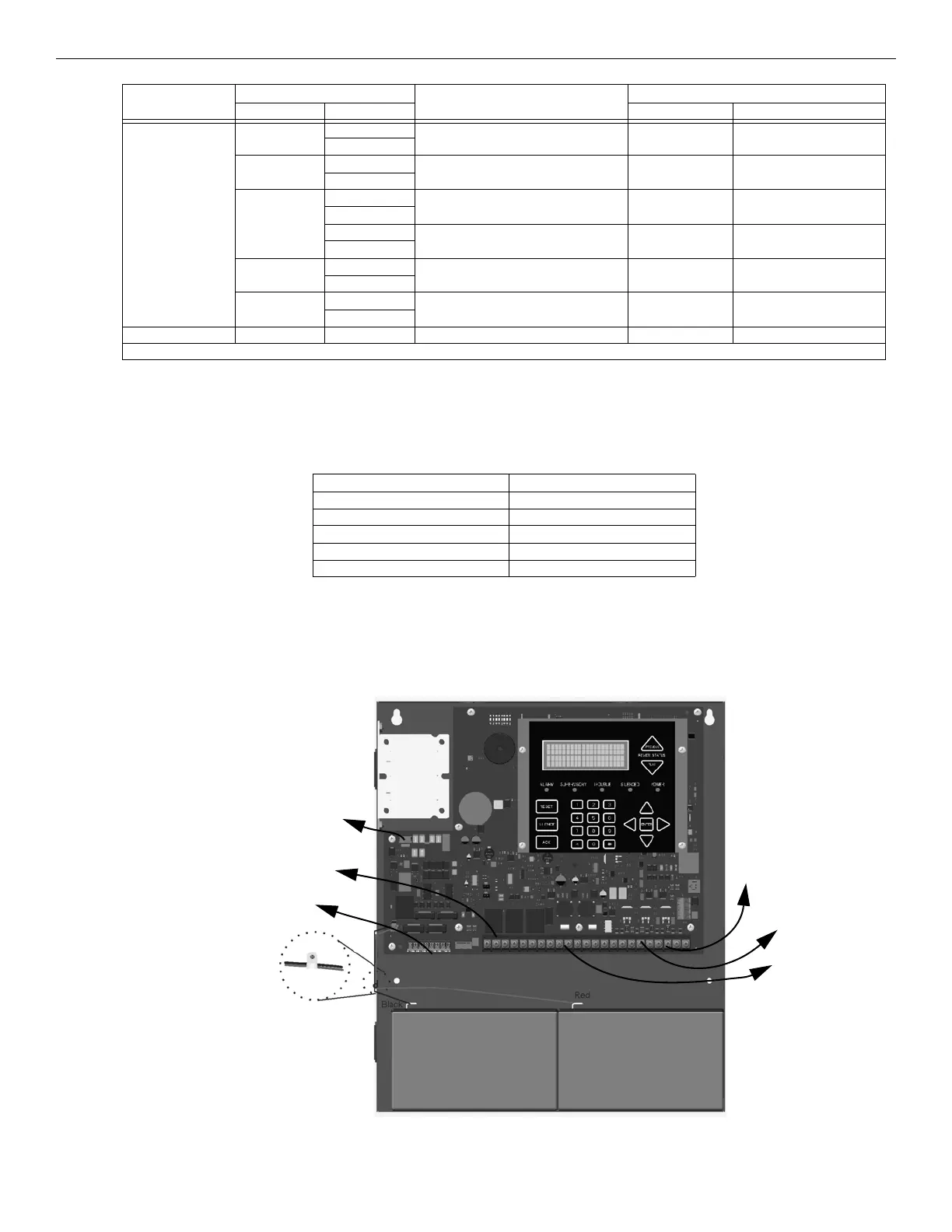
• Route the wiring around the inside perimeter of the cabinet. It should not cross the circuit board where it could induce noise into the
sensitive microelectronics or pick up unwanted RF noise from the high speed circuits. See Figure 3.1 for an example.
• High frequency noise, such as that produced by the inductive reactance of a speaker or bell, can also be reduced by running the wire
through ferrite shield beads or by wrapping it around a ferrite toroid.
Figure 3.1 Wire Routing Example
Terminal Block 2 SLC OUT – SLC terminals 32 VDC 100 mA
+
SLC PROG – Used for programming SLC Detectors 32 VDC 100 mA
+
SBUS – SBUS Power 27.4 VDC 0.5 A
+
A SBUS Communication 5 VDC 100 mA
B
NAC1* – Notification Appliance Circuit/Auxiliary
power
27.4 VDC 1 Amp NAC or Aux power
+
NAC2* – Notification Appliance Circuit/Auxiliary
power
27.4 VDC 1 Amp NAC or Aux power
+
P7 Data Network Used for FIK-NIC 24 VDC 21 mA
Note: Regulated NAC application. When programmed for releasing, NAC are Special Application.
Terminal No.
Label
Description
Rating
Group Individual Voltage Current
Table 3.1 Terminal Descriptions and Electrical Specifications (Continued)
High voltage AC power Terminals
SLC loops
Audio input/output Phone line circuits
Notification circuits NAC1 through NAC2
SBUS
Relay circuits
Table 3.2 Wiring Specifications
Relay
NAC / Aux Power
Outputs
SBUS
Phone
SLC IN/OUT
AC Power
Input
Devices
Lines
Outputs
Battery
Battery
1/4” spacing must
be maintained
between each of
these circuit types;
as well as between
power-limited and
non-power-limited
circuits.