72 FCP-75 Manual — P/N LS10147-003FK-E:A 3/17/2021
Programming Overview Mapping Overview
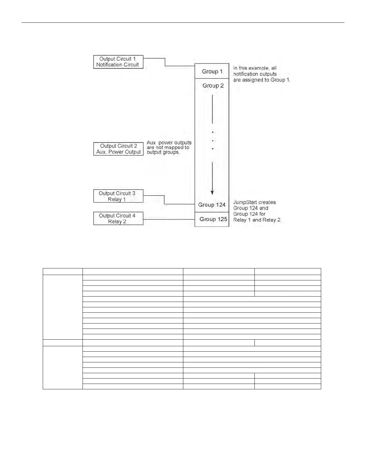
8.2.2 Output Circuit Mapping
Figure 8.3 is a simple example showing how to assign notification and relay output circuits to groups. For an example of a simple floor
above/floor below application, see Figure 8.5.
Figure 8.3 Assigning Output Circuits to Groups (Example)
8.2.3 Event Mapping
There are 11 types of Zone events, 14 types of Panel events, and 6 types of Site events that can be mapped (see Table 8.1). For each event
type, you can activate the Output Groups with specific Output Patterns. Mapping examples are shown in Figure 8.4, Figure 8.5, &
Figure 8.6.
System Zone Panel Site
Fire
Manual Pull Alarm System Aux 1 Alarm Fire Drill
Water Flow Alarm System Aux 2 Alarm General Fire Alarm
Detector Alarm (heat or smoke detectors) General Fire Supervisory
Zone Aux 1 Alarm General Fire Pre-Alarm
Zone Aux 2 Alarm
Interlock Alert
Interlock Release
Pre-Alarm
Fire Supervisory
Status Point
CO Alarm
CO Supervisory
Emergency
Advisory
Trouble SBUS Expander Trouble General Trouble
Status Point Active SBUS Class A Trouble Site Silenced
SLC Loop Trouble
AC Loss Trouble F1 Key Active
Battery Trouble F2 Key Active
Ground Fault Trouble F3 Key Active
Phone Line Trouble F4 Key Active
Reporting Account Trouble
Table 8.1 Event Types