FCP-75 Manual — P/N:LS10147-003FK-E:A 3/17/2021 47
Remote Station Applications Control Panel Installation
It is not possible to reset the remote indication until you clear the condition and reset the control panel.
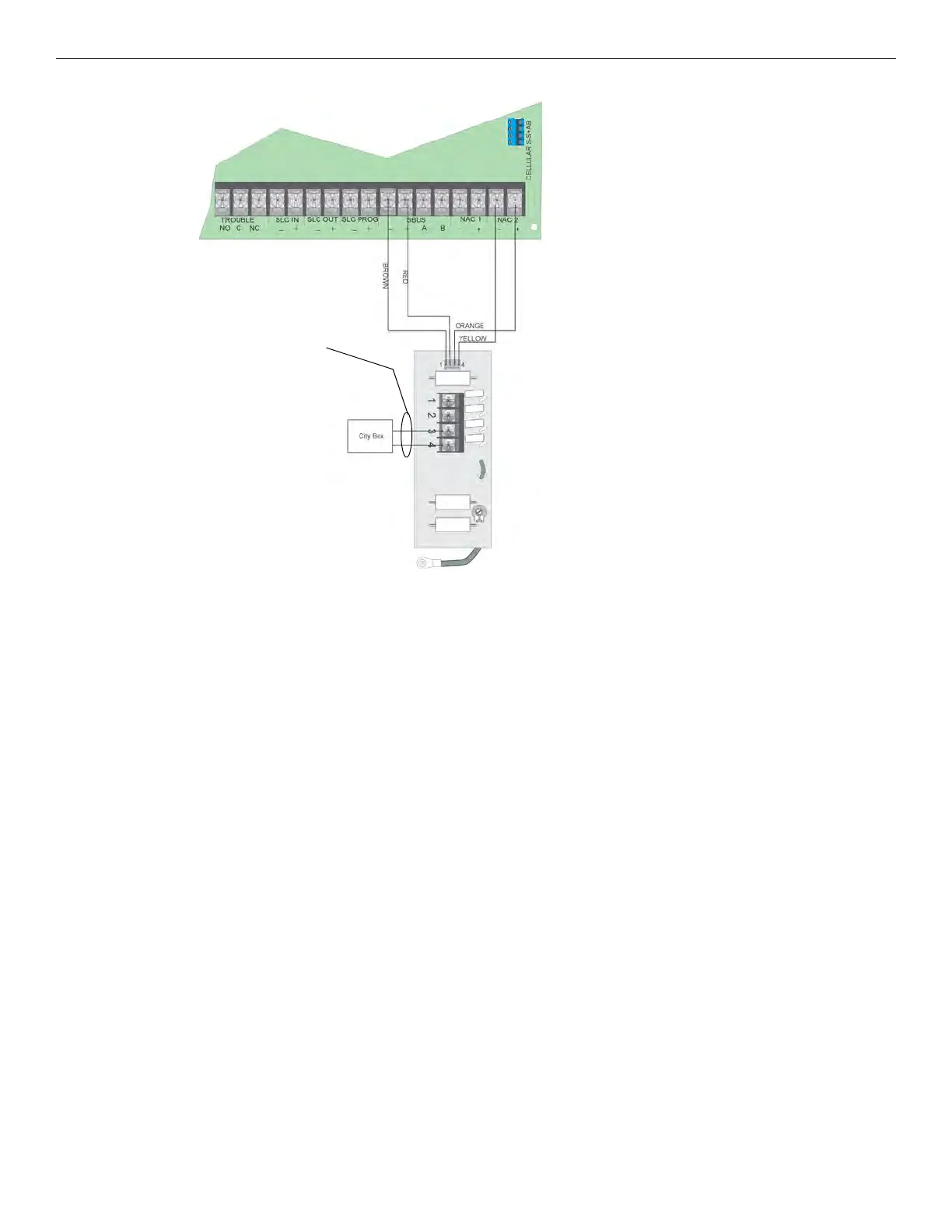
Figure 4.46 City Box Connection
4.15.3 NFPA 72 Polarity Reversal
Using the 5220 Module
When the 5220 is wired and programmed for polarity reversal, it reports alarm and trouble events to a remote site. Alarms will override trou-
ble conditions and it will not be possible to reset the remote indicator until the condition is cleared and the control panel is reset.
If an alarm condition occurs, the alarm relay will close, overriding the trouble condition.
Standby Current: 100mA
Alarm: 100mA
Max. Voltage: 27.4VDC
To install the 5220 for polarity reversal, follow the steps below:
1. Locate the knockout on the right side of the control panel cabinet to connect the 5220 using a short piece of conduit (must not exceed 20
feet in length).
2. Wire the 5220 to the control panel using the four-wire pigtail provided as shown in Figure 4.47. This diagram also shows how to
connect the 5220 to the remote indicator. Do not install an EOL resistor in the terminals of the NAC circuit used for this application.
3. Connect earth ground wire to the 5220 chassis with mounting screw.
4. Program the NAC circuit used as continuous and non-silencing. Refer to Section 9.5 for point programming, Section 9.4 for group
settings, and Section 9.3 for zone settings and mapping.
Non-Supervised
Non-power-limited
Note: NAC Circuit 2 Used as an Example.
Either NAC Circuit Can Be Used.