Wiring Requirements for SLC Devices Fike IDP and SWIFT SLC Device Installation
FCP-75 Manual — P/N:LS10147-003FK-E:A 3/17/2021 67
.
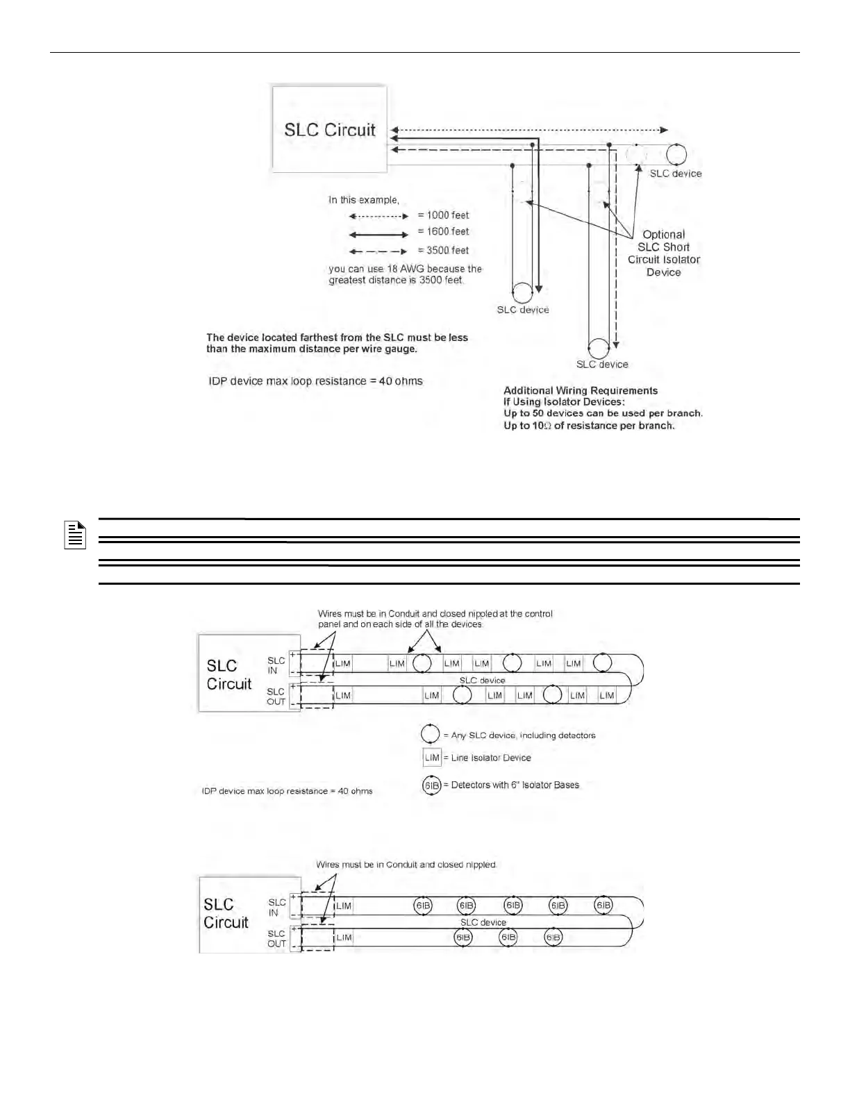
Figure 7.2 Calculating Wire Run Length for a T-tap
7.4.3 Wiring SLC in Class A Configuration
Figure 7.3 illustrates how to wire the SLC loop for Class A installations.
.
Figure 7.3 Class A SLC Configuration
NOTE 1: Style 6 does not use short circuit isolator devices.
NOTE 2: Style 7 requires an isolator module as the first device on the in and the out loop.
NOTE 3: No t-taps allowed on class A SLC loops.