Calculating Current Draw and Standby Battery Before You Begin Installing
FCP-75 Manual — P/N:LS10147-003FK-E:A 3/17/2021 19
1. Total does not include isolator devices or accessory bases.
2. If using door holders, you do not need to consider door holder current for alarm/battery standby, because power is removed during
that time. However, during normal operation, door holders draw current and must be included in the 2.5A total alarm current (1.0A
for all other conditions) that can be drawn from the panel.
3. Use next size battery with capacity greater than required.
4. The FIK-2351R is sold separately from the DNR. Current draw for the DNR + FIK-2351R is calculated by increasing the “Number
of Devices” column for each FIK-2351R used with a DNR.
5. The DNR housing does not include a Relay circuit board. If a relay is needed, be sure to add one to the FIK-M500R & FIK-2351R
“Number of Devices” column for each DNR used for correct current calculations.
6. The FACP can only support 5 devices w/LED’s on. This current draw has been added to the panels alarm current.
Accessories Modules
FIK-RA2000 Remote LCD Annunciator (8 max.) Standby: 25 mA mA
Alarm: 50 mA mA
FIK-RA100 Remote LCD Annunciator Standby: 20 mA mA
Alarm: 25 mA mA
FIK-RA1000R Remote LCD Annunciator Standby: 20 mA mA
Alarm: 25 mA mA
FIK-5824 Serial / Parallel Module (4 max.) Standby/Alarm: 45mA mA mA
FIK-5496 NAC Expander (8 max.) Standby/Alarm: 10 mA mA mA
FIK-RPS1000 Power Supply Standby/Alarm: 10 mA mA mA
FIK-5865-4 LED Annunciator
(with reset and silence switches)
(8 max.) Standby: 35 mA mA
Alarm: 145 mA mA
FIK-5865-3 LED Annunciator Standby: 35 mA mA
Alarm: 145 mA mA
FIK-5880 LED I/O Module Standby: 35 mA mA
Alarm: 200 mA mA
FIK-5883 Relay Interface (32 max.) Standby: 0 mA mA
Alarm: 220 mA
(22 mA per relay)
mA
FIK-NIC Network Interface Card (1 Max.) Standby/Alarm: 21 mA mA mA
FIK-FML Fiber Optic Multi Mode (1 Max.) Standby/Alarm: 53 mA mA mA
FIK-FSL Fiber Optic Single Mode (1 Max.) Standby/Alarm: 79 mA mA mA
Wireless Modules
FIK-W-WGI Wireless Gateway Max current using external supply 40 mA mA mA
Max current SLC Power 24 mA mA mA
Total System Current
Auxiliary Devices
2
Refer to devices manual for current rating.
Alarm/Standby: mA mA mA
Alarm/Standby: mA mA mA
Alarm/Standby: mA mA mA
Alarm/Standby: mA mA mA
Auxiliary Devices Current
Notification Appliance Circuits Refer to device manual for current rating.
Alarm: mA
mA
Alarm: mA
mA
Alarm: mA
mA
Notification Appliances Current
mA
Total current ratings of all devices in system (line A + line B + C) mA mA
Total current ratings converted to amperes (line D x.001): A A
Number of standby hours (24 or 60 for NFPA 72, chapter 1, 1-5.2.5): H
Multiply lines E and F. Total standby AH AH
Alarm sounding period in hours. (For example, 5 minutes =.0833 hours) H
Multiply lines E and H. Total alarm AH
AH
Add lines G and I.
3
AH
Multiply by the Derating Factor x 1.25
Total ampere hours required AH
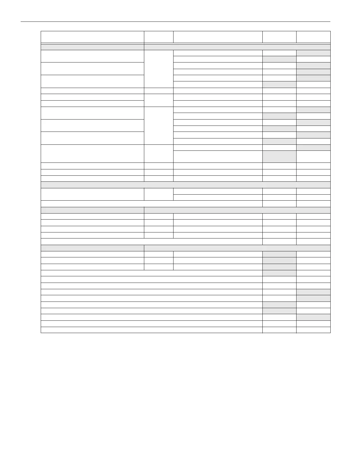
Device # of Devices Current per Device
Standby
Current
Alarm Current
Table 3.3 Current Calculation Worksheet for Fike IDP Devices (Continued)