158
6
OPTIONAL EQUIPMENT
id.:
DB 460 REV. 00 02/01/2015
6.2.3.
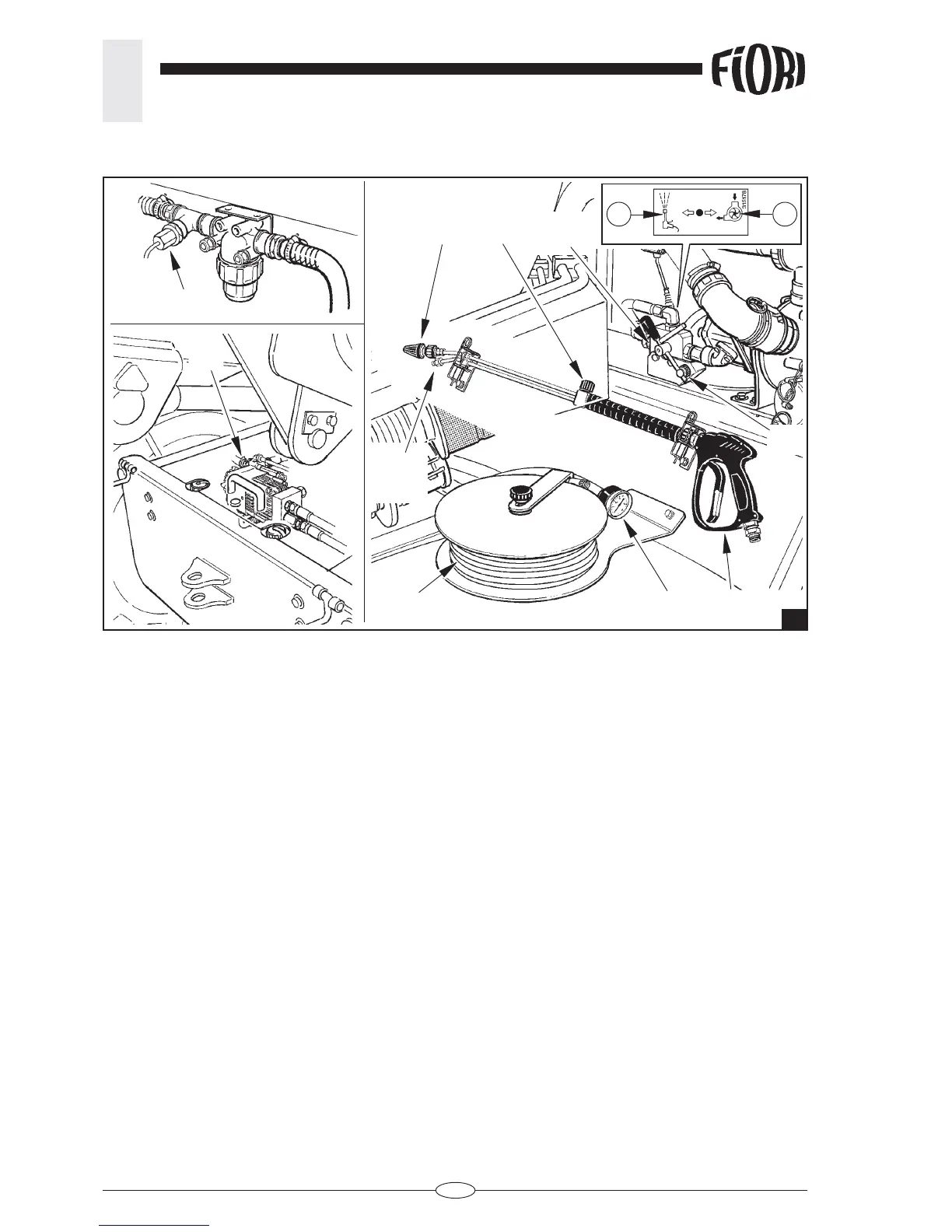
REFERENCES AND DESCRIPTIONS OF THE MAIN DEVICES (fi g. 2).
The following parts control water feed and distribution through the power jet cleaner:
A - Power jet cleaner.
Positioned behind the cabin under the water suction pump.
B - Low-pressure nozzle.
C - High-pressure nozzle.
D – Pressure regulating valve.
Turning the valve clockwise releases the pressure and anticlockwise increases the pressure.
E - Switch
Position “1” - Water suction pump activation.
Position “2”- Power jet cleaner pump activation.
F - High-pressure hose.
Connects the pump to the power jet cleaner.
G - Water pressure gauge.
Shows the pressure of the water fl owing from the pump.
H - Water pump.
Positioned at the rear of the chassis in the tool compartment.
I - Switch
Turn switch lever E to position “2” to trigger the switch that enables water sensor L. If the sensor detects
that there is no water fl ow due to the empty tank, pump H automatically stops.
2
E
DC
B
F
G A
H
12
L
I
 Loading...