Installation Instructions
30.10.12 Kapitel/Chapter 6: Installation Instructions Seite/Page 87
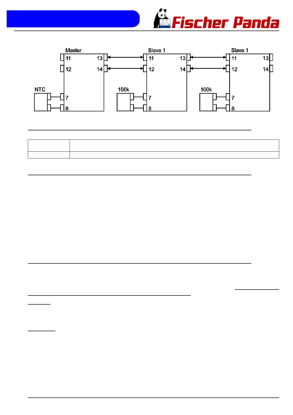
Fig. 6.12.2-1:
6.12.3 Function of the clamps for the Master-Slave-Operation
6.12.4 Remote controlled switching on and off of the fan controller
he fan controller can be switched on and/or off over the connection „ON“ (clamp 9). If at connection „ON“ lies the
same voltage as at the connection „BAT +“, the fan controller is switched on. If at connection „ON“ lies no voltage,
the fan controller is switched off. If this option is not needed, then the connection „ON“ can connected directly on the
printed circuit board, over the solder joint J101, with the connection „BAT +“.
• J101 closed: Fan control always on
• J101 open: Fan control only on if operation voltage at
connection „ON“
The solder joint J101 is seen from the direct line clamp directly behind the main safety device (main fuse) on the
printed circuit board.
6.12.5 12V / 24V - Operation
For 12V and/or 24V-operation the pre-resistor for the operating voltage of control electronics must be adapted. This
pre-resistor consists of two resistances, which are connected in series. For 12V-operation one of these resistances
is short circuit with the solder joint J102. For 24V-Betrieb the solder joint J102 must be opened. Additionally different
safety devices (fuses) must be installed depending upon operating voltage.
Main fuse (flat fuse on the printed circuit board):
12V-operation: 50A flat fuse
24V-operation: 30A flat fuse
Output fuse
(plug fuse on the terminal block, each two pieces):
12V-operation: 25A plug fuse
24V-operation: 20A plug fuse
Clamp 11+12: Control input for slave operation. Clamp 11 is the positive input. Clamp 12 is the negative input. The input is floating, so
that via this input connected fan controllers of the same source can be supplied, without a ground loop develops.
Clamp 13+14: Output for the master-slave-operation. At clamp 13 is the signal and at clamp 14 is ground.