Seite/Page 4 Panda_6500_7mini_PMS_eng.R01 - Kapitel/Chapter A: 22.3.11
3.4.3.2 Arrangements for deconservation after a medium-term standstill (3 to 6 months)................... 36
3.4.4 Arrangements at a long-term standstill / shutdown ........................................................... 36
3.4.4.1 Arrangements for conservation: ............................................................................................... 36
3.4.4.2 Arrangements after a long-term standstill (shutdown) / recommissioning (more than 6 months): 37
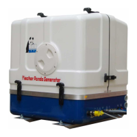
4 The Panda Generator...................................................................................................39
4.1 Type plate at the Generator ........................................................................................... 39
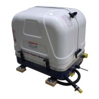
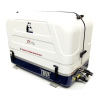
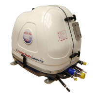
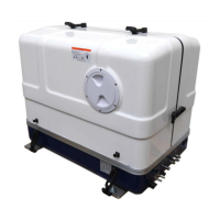
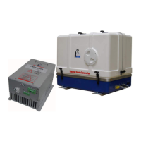
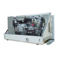
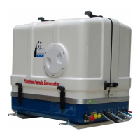
4.2 Description of the Generator ......................................................................................... 40
4.2.1 Right Side View ................................................................................................................. 40
4.2.2 Left Side View .................................................................................................................... 41
4.2.3 Front View ......................................................................................................................... 42
4.2.4 Back View .......................................................................................................................... 43
4.2.5 View from above ................................................................................................................ 44
4.3 Details of Functional Units ............................................................................................ 45
4.3.1 Remote control panel ........................................................................................................ 45
4.3.2 Components of the Cooling System (Raw Water) ............................................................. 45
4.3.3 Components of the Cooling System (Fresh water) ............................................................ 47
4.3.4 Components of Fuel System ............................................................................................. 49
4.3.5 Components of combustion air .......................................................................................... 50
4.3.6 Components of Electrical System ...................................................................................... 52
4.3.7 Sensors and Switches for Operation Surveillance ............................................................ 54
4.3.8 Components of Oil Circuit .................................................................................................. 55
4.4 Operation of the generator - see separate remote control panel manual ................. 57
4.4.1 Daily routine checks before starting - see separate remote control panel manual. ........... 57
4.4.2 Starting Generator - see separate remote control panel manual. ..................................... 57
4.4.3 Stopping Generator - see separate remote control panel manual. .................................... 57
5 Installation Instructions...............................................................................................59
5.1 Personal requirements ................................................................................................... 59
5.1.1 Hazard notes for the installation ........................................................................................ 59
5.2 Preparing the base - Placement ................................................................................... 61
5.2.1 Advice for optimal sound insulation ................................................................................... 61
5.3 Generator Connections .................................................................................................. 61
5.4 Installation of the cooling system - raw water ............................................................. 62
5.4.1 General Information ........................................................................................................... 62
5.4.2 Installation of the thru hull fitting in Yachts ........................................................................ 62
5.4.3 Quality of the Raw Water Sucking In Line ......................................................................... 62
5.4.4 Generator Installation above Waterline ........................................................................... . 63
5.4.5 Generator Installation below Water-Line ......................................................................... . 64
5.4.6 Generator Housing cooled by Raw Water ......................................................................... 65
5.4.7 Indirect Cooling of the Genset Housing (by the Heat Exchanger) ................................... . 66
5.5 Installation of the cooling system - fresh water .......................................................... 66
5.5.1 Position of the external cooling water expansion tank ....................................................... 66
5.5.2 Ventilating at the first filling of the Internal Cooling Water Circuit ...................................... 67
5.5.3 Pressure Test for Controlling the Cooling Water Circuit .................................................... 68
5.5.4 Scheme for Freshwater Circuit at Two Circuit Cooling System ....................................... . 69
5.6 Installation of the water cooled exhaust system ......................................................... 70
5.6.1 Installation of the standard exhaust system ...................................................................... 70
5.6.2 .Installation of the water collector ...................................................................................... 70
5.6.3 Possible cause: Exhaust duct ............................................................................................ 71
5.6.4 Possible cause: Coolant duct ............................................................................................ 71
5.6.5 Installation area of exhaust water collector ....................................................................... 71
5.6.5.1 The volume of the exhaust water collector............................................................................... 72
5.6.5.2 Position of the water collector.................................................................................................... 74
5.6.5.3 Example of the installation of the water collector off-center and possible effects: .................... 76
5.6.6 Exhaust / water separator .................................................................................................. 78
5.6.7 Installation exhaust water separator ................................................................................ . 80
5.7 Installation of the fuel system ....................................................................................... 82