150718 PL YFLY rev A_Frame | Aug us t 7, 20 15 5:0 6 P M
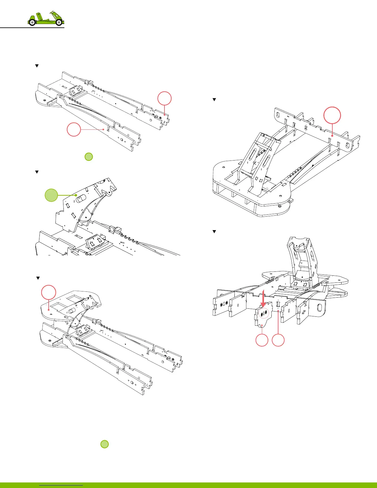
20. Repeat steps 18 and 19 using
‒ Part 42
‒ Part 43
Note the letter L should face part 41, away from the centerline of the go-kart.
21. Using a mallet, tap
2
into the tab connections in the
center of part 44.
Note the orientation and location of the assembly.
22. Using a mallet, tap part 45 slots into the tab connections
of go‑kart front‑end (parts 40‑43).
Note the correct orientation for part 45; the bushings face(down) part 44.
23. Secure part 45 using screws.
‒ Use 12 screws.
‒ Total of 12 locations.
24. Flip the assembly over and using a mallet, tap any
unseated tabs into place.
‒ It is best to do this with
2
hanging o the edge of
a table or saw horses.
25. Secure part 44 to the assembly using screws.
‒ There is a purposeful gap in alignment to allow part 51
to sit ush with the assembly.
‒ Use 12 screws.
‒ Total of 12 locations.
26. Flip the assembly right side up again.
27. Using a mallet, tap part 46 into place.
Note the orientation and position the tabs on part 46.
28. Using a mallet, tap part 47 into the center slot of part 46.
Note the orientation and position of part 47.
29. Secure parts 46 to part 47 using screws.
‒ Use 2 screws.
‒ Total of 2 locations.
43
42
2
45
46
47 46
34
9 Frame Assembly