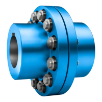
● Take care not to damage the shaft sealing rings or shaft running surfaces when fitting the
coupling components.
● If you must heat up the input and output elements before assembly, the joining temperatures
required are listed in the dimension drawings in the coupling operating instructions.
● Unless otherwise specified, heat the coupling parts by an induction heater, with a torch or
in an oven.
● Use heat shields designed to protect against radiant heat in order to safeguard the shaft
sealing rings against damage or heating to above 100 °C.
● The elements must be quickly pulled onto the shaft as far as stated in the dimension drawing
prepared in accordance with order specifications.
● Use suitable hoisting gear to place the gear unit in position.
NOTICE
Poor alignment
The gear unit or individual components can be damaged as a result of poor alignment.
When installing and mounting the drive ensure that the individual components are precisely
aligned with one another.
Inadmissibly high alignment errors of the shaft ends to be connected as a result of angular
or axial offset result in premature wear and material damage. Base frames or substructures
that are too soft can cause the coupling parts to become radially or axially displaced during
operation. This displacement is not measurable when the drive is at a standstill.
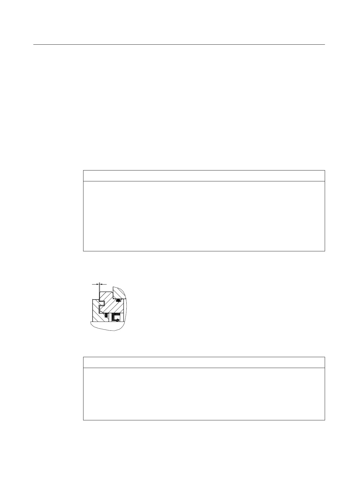
The following figure shows the gap dimension at the grease labyrinth:
Figure 5-1 Gap dimension at grease labyrinth
NOTICE
Sparking, inadmissible temperature rise and shaft seal wear due to insufficient gap dimension
An insufficient gap dimension can cause sparking, inadmissible temperature rise and shaft
seal wear.
If the shaft is sealed by taconite or Tacolab seals, make sure that the set gap dimension of
1
+0.5
mm at the grease labyrinth is not altered when the input and output elements (e.g.
coupling parts) are installed. Rotating and stationary parts must not touch.
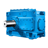
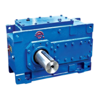
Assembly
5.3 Gear unit assembly
Gear unit 5118en
Operating Instructions 10/2017 59