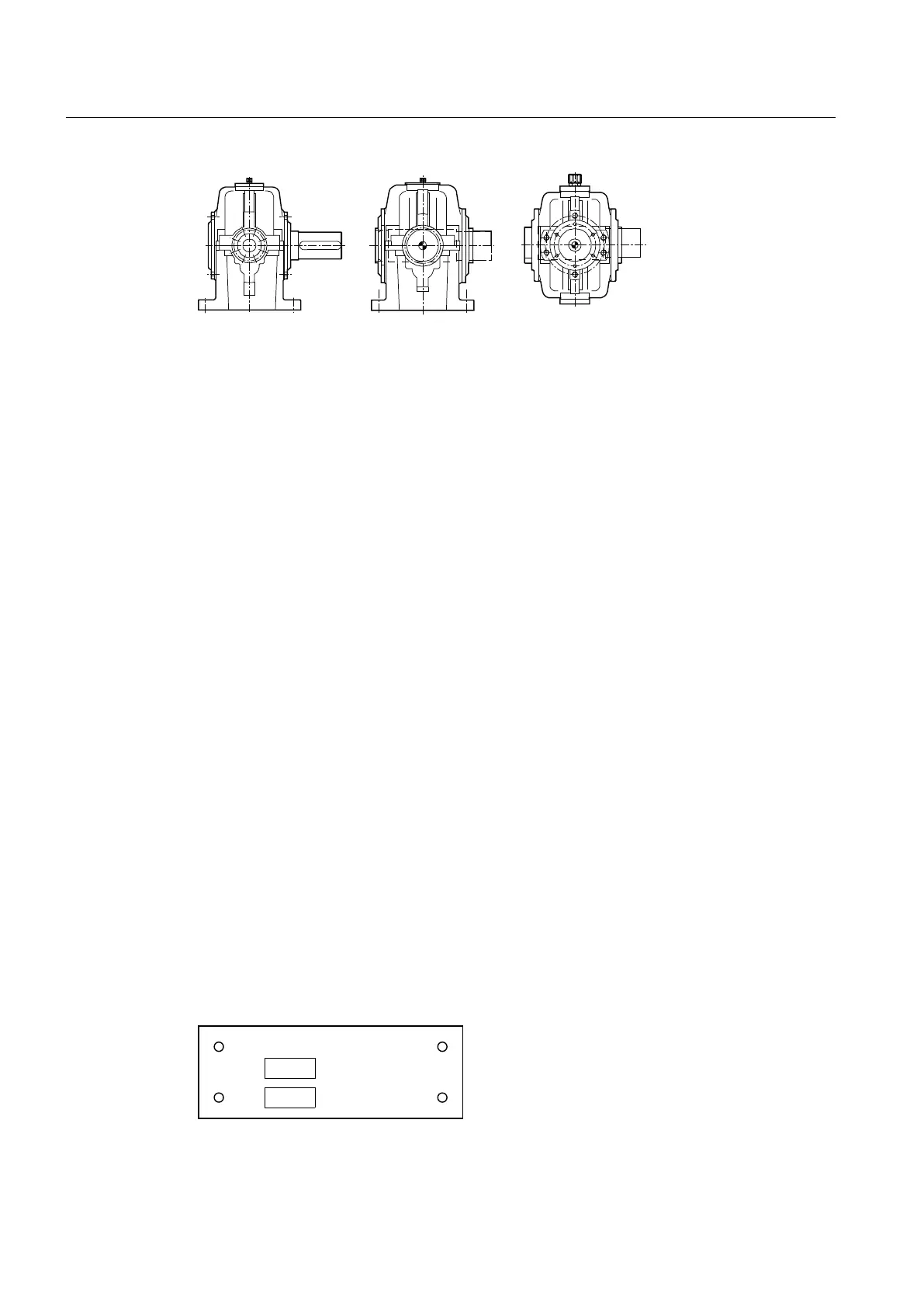
Figure 3-1 Output shaft versions
Further information
Additional information and a detailed illustrated description can be found in the dimension
drawing in the complete gear unit documentation.
3.3 Housing
Introduction
The housing is in two parts, and is manufactured out of cast iron. When specified, the housing
can also be manufactured out of steel.
The gear unit housing has the following features:
● Attachment points for transporting the gear unit
● Inspection and assembly cover
● Oil filling point for refilling with oil
● Oil sight glass, oil level indicator or dipstick for checking the oil level
● Oil drain screw or oil drain valve for changing the oil
● Venting screw, air filter or wet-air filter for ventilation and bleeding
Further information
Additional information and a detailed illustrated description of the gear unit can be found in the
dimension drawing provided in the complete gear unit documentation.
The lubrication points are designated using the following sign:
RSHUDWLQJKRXUVDIWHU
/XEULFDWLRQSRLQW
JOLWKLXPVRDSEDVHGJUHDVH
Figure 3-2 Sign: Lubrication point
Description
3.3 Housing
REDUREX Gear unit 5200en
22 Operating Instructions 03/2019