0
0
r
$
%
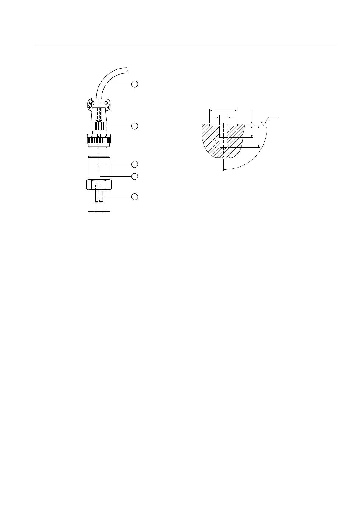
① Shielded cable (oil-proof) ④ Sensitivity specification
② MIL-spec connector ⑤ Set screw
③ Acceleration sensor
Figure 3-13 Complete acceleration sensor (A) and threaded connector (B)
Further information
Further information and a detailed illustration of the gear unit with attached sensors can be
found in the dimension drawing in the complete documentation for the gear unit.
Further information about the sensors can be found in the operating instructions for the sensors.
3.16 Auxiliary drive
For specific applications, the gear unit can be equipped with an auxiliary drive. The auxiliary
drive enables the main gear unit to be operated at a lower output speed in the same direction
of rotation. Either Flender or the customer provides the auxiliary drive. The auxiliary drive is
connected to the main gear unit through an overrunning clutch. The auxiliary drive is mounted
onto a connection flange, which in turn is attached to the main gear unit. The overrunning clutch
is located in a separate oil space. The auxiliary drive has its own oil circuit, which is separate
from that of the main gear unit.
Before connecting the motor, identify the phase sequence of the three-phase mains using a
phase sequence instrument. Then connect the motor so that it rotates in the defined direction.
Observe the note attached to the gear unit.
Description
3.16 Auxiliary drive
REDUREX Gear unit 5200en
Operating Instructions 03/2019 41