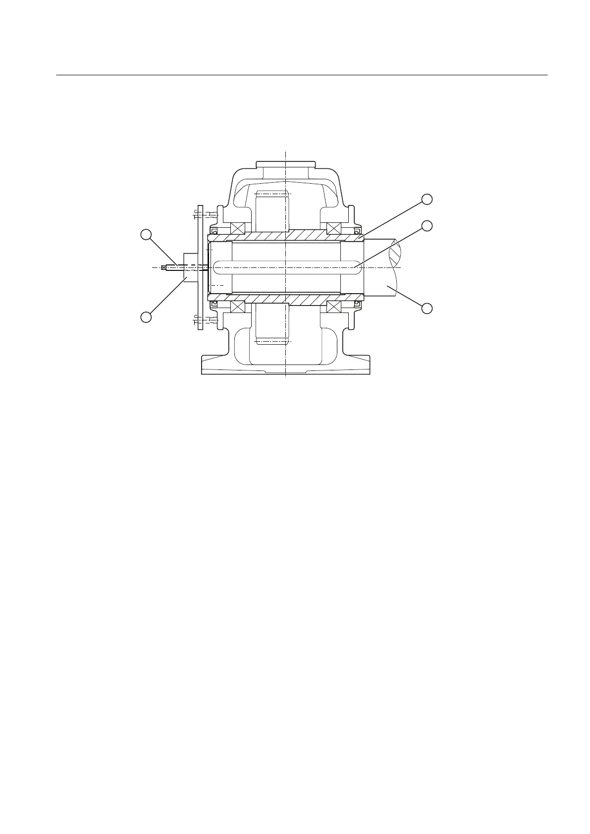
The following diagram shows the dismantling procedure using hydraulic pulling equipment for
gear units with hollow shaft and parallel keyway:
① Screw spindle ④ Machine shaft
② Hollow shaft ⑤ hydraulic pulling equipment
③ Parallel key
Figure 5-8 Dismantling using hydraulic pulling equipment
5.5 Shaft-mounted gear unit with hollow shaft and shrink disk
Introduction
The shaft end of the driven machine shaft (material C60+N or higher strength) should have a
hole centred in its end face as defined by DIN 332, form DS (with thread). Depending on the
version, hollow shafts can be equipped with DU bushings to guide the shaft.
The shrink disks are not supplied with the gear unit. They can be supplied when requested.
Further information
Further information about the connection dimensions of the driven machine shaft can be found
in the dimension drawing in the complete documentation for the gear unit.
Mounting
5.5 Shaft-mounted gear unit with hollow shaft and shrink disk
REDUREX Gear unit 5200en
Operating Instructions 03/2019 67