Gear unit equipment
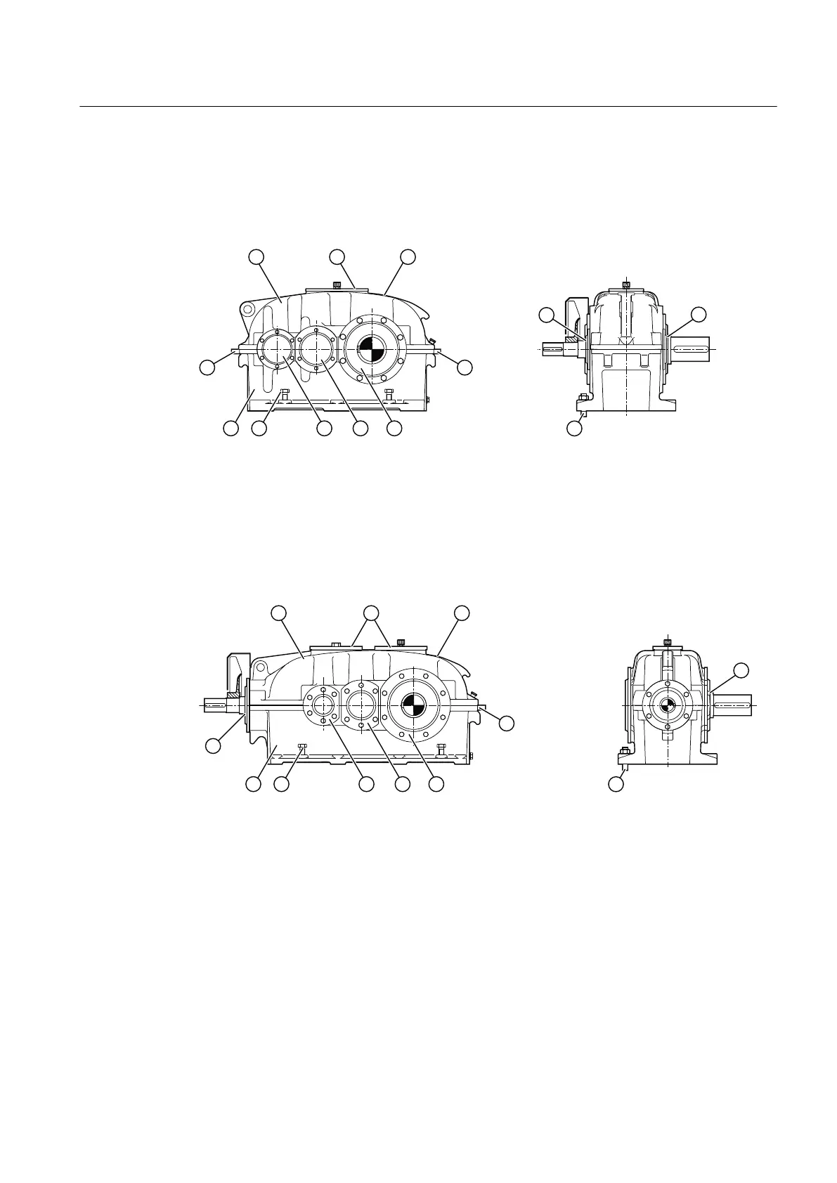
The diagram below shows the gear unit equipment on type S.N gear units:
① Upper housing section ⑥ Pressure screws (≥ 360)
② Inspection and/or assembly cover ⑦ Lower housing section
③ Rating plate ⑧ Shaft seals
④ Alignment surfaces (≥ 360) ⑨ Gear unit fastening
⑤ Cover
Figure 3-3 Gear unit equipment for type S.N gear units
The diagram below shows the gear unit equipment on type K.N gear units:
① Upper housing section ⑥ Pressure screws (≥ 360)
② Inspection and/or assembly cover ⑦ Lower housing section
③ Rating plate ⑧ Shaft seals
④ Alignment surfaces (≥ 360) ⑨ Gear unit fastening
⑤ Cover
Figure 3-4 Gear unit equipment for type K.N gear units
Further information
Additional information and a detailed illustrated description of the gear unit can be found in the
dimension drawing provided in the complete gear unit documentation.
Description
3.3 Housing
REDUREX Gear unit 5200en
Operating Instructions 03/2019 23