Further information
You will find further information on the position of the torque arm in the dimension drawing,
which is part of the complete documentation of the gear unit.
5.4 Shaft-mounted gear unit with hollow shaft and parallel keyway
The shaft end of the driven machine shaft (material C60+N or higher strength) must have a
parallel key as defined by DIN 6885, Part 1, form A. Furthermore, it should have a hole centred
in its end face as defined by DIN 332, form DS (with thread). The connection dimensions for the
driven machine shaft can be found in the dimension drawing in the complete documentation.
View
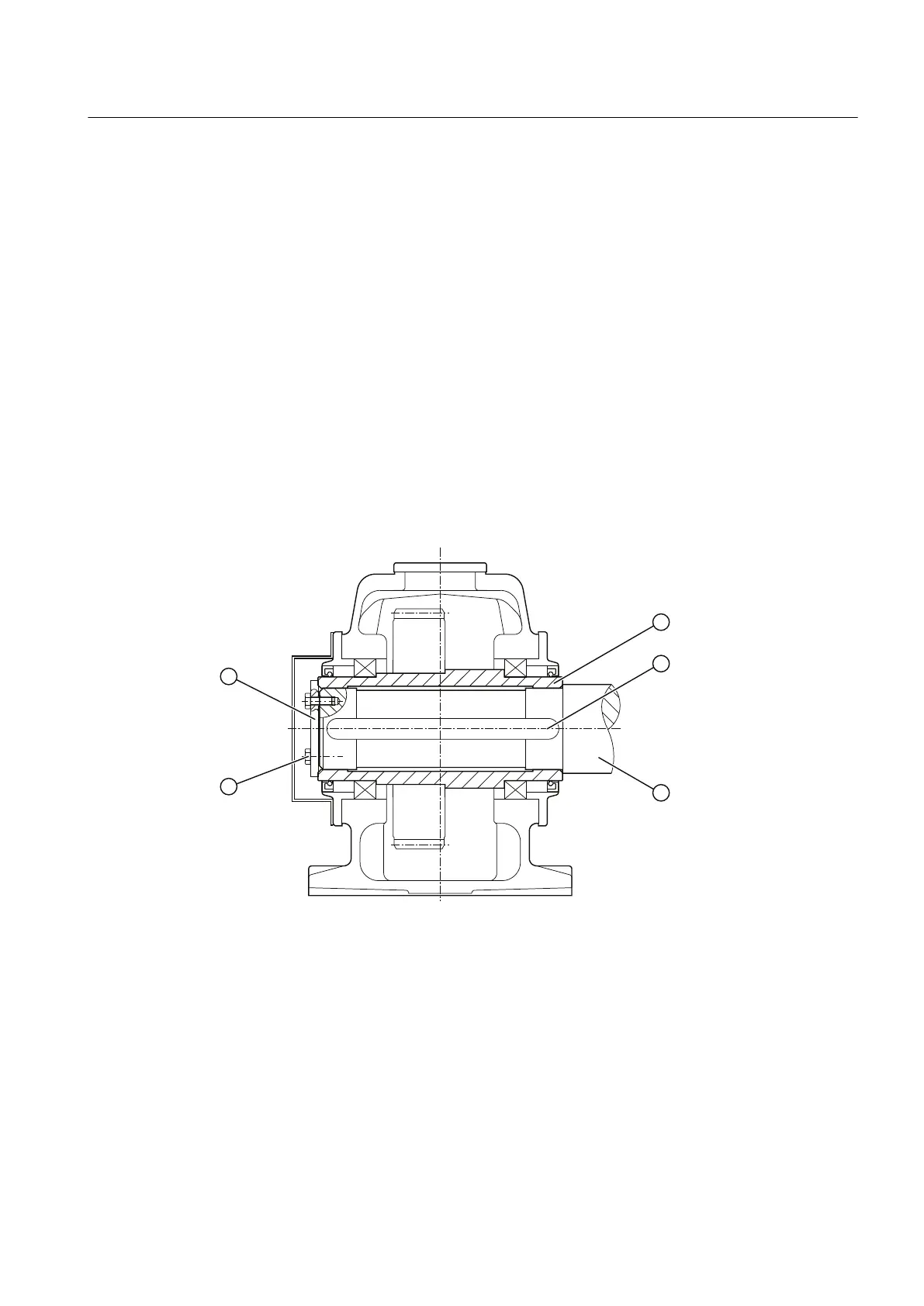
The following diagram shows a gear unit with hollow shaft and parallel keyway:
① End plate ④ Machine shaft
② Hollow shaft ⑤ Bolts
③ Parallel key
Figure 5-6 Gear unit with a hollow shaft and parallel keyway
Mounting
5.4 Shaft-mounted gear unit with hollow shaft and parallel keyway
REDUREX Gear unit 5200en
Operating Instructions 03/2019 63