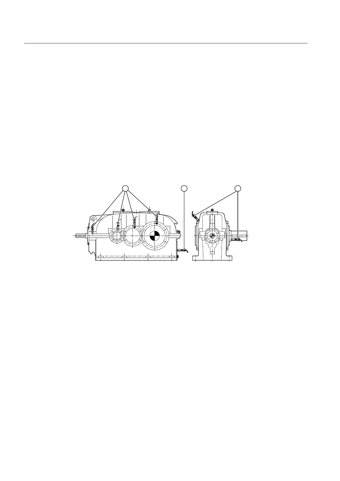
Further information
Further information and a detailed illustration of the gear unit and the position of the mounted
components can be found in the dimension drawing in the complete documentation for the gear
unit.
Further information about bearing monitoring using a Pt 100 resistance thermometer (such as
control instructions) and the technical data can be found in the operating instructions for the Pt
100 resistance thermometer and in the list of equipment in the complete documentation for the
gear unit.
3.15.2 Bearing monitoring by acceleration sensor
Depending on the order specification, the gear unit can be supplied with threaded holes in
which acceleration sensors can be inserted. These threaded holes have an M6 or M8 thread
depending on the variant.
① Shock-pulse transducer
Figure 3-12 Bearing monitoring using a shock-pulse transducer
The following diagram shows the complete acceleration sensor (A) and the threaded connector
(B):
Description
3.15 Bearing monitoring
REDUREX Gear unit 5200en
40 Operating Instructions 03/2019