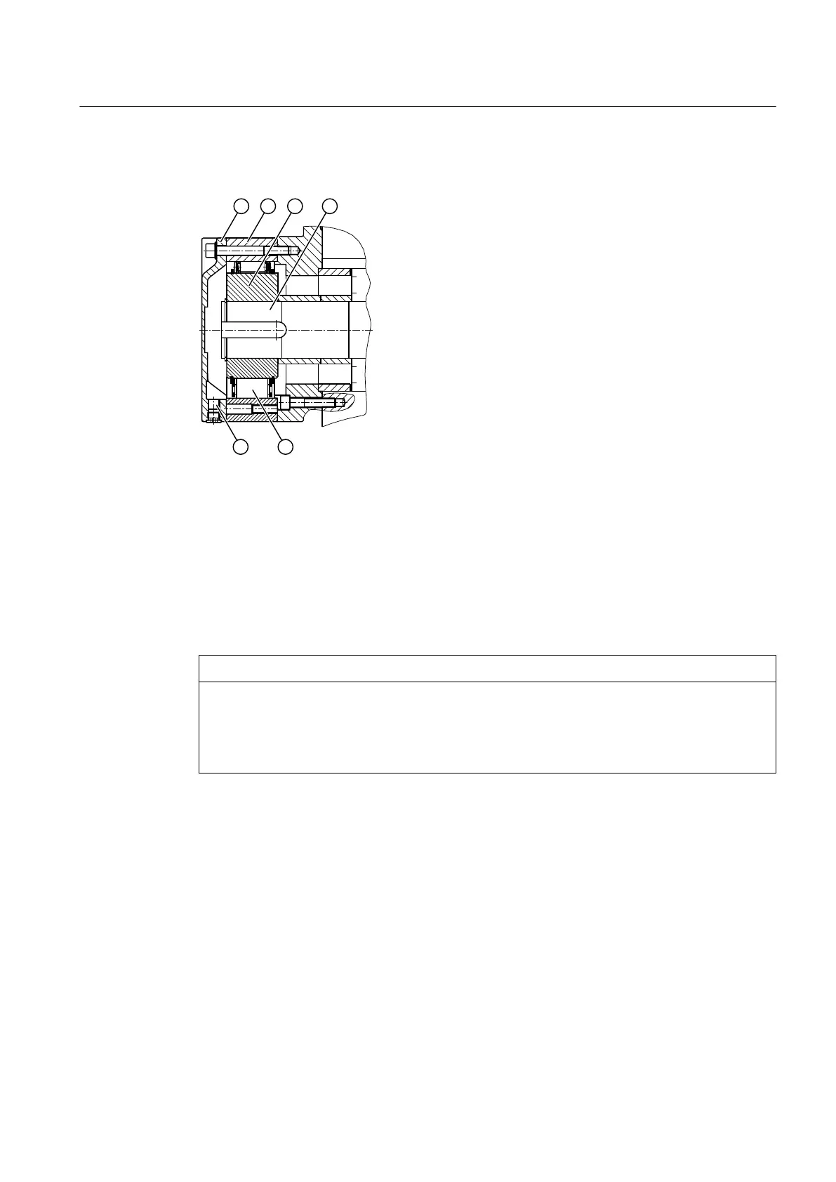
The diagram below shows a backstop:
① Cover ④ Shaft
② Outer ring ⑤ Cage with sprags
③ Inner ring ⑥ Residual oil drain
Figure 3-10 Backstop
Before connecting the motor, identify the phase sequence of the three-phase mains using a
phase sequence instrument. Connect the motor corresponding to the defined direction of
rotation.
The blocking direction of the backstop can be changed by turning over the cage. You must
always contact Flender in advance if you wish to change the blocking direction.
NOTICE
Damage to the backstop and gear unit due incorrect direction of rotation
Damage to the backstop and gear unit due incorrect direction of rotation possible.
Do not operate the motor adversely to the blocking direction of the gear unit. Observe the note
attached to the gear unit.
3.9 Couplings
Flexible couplings or safety couplings are generally used at the input end of the gear unit.
Use of rigid couplings or other input or output elements that generate additional radial or axial
forces (e.g. gear wheels, belt pulleys, flywheels or hydraulic couplings) must be agreed
contractually.
Description
3.9 Couplings
REDUREX Gear unit 5200en
Operating Instructions 03/2019 35