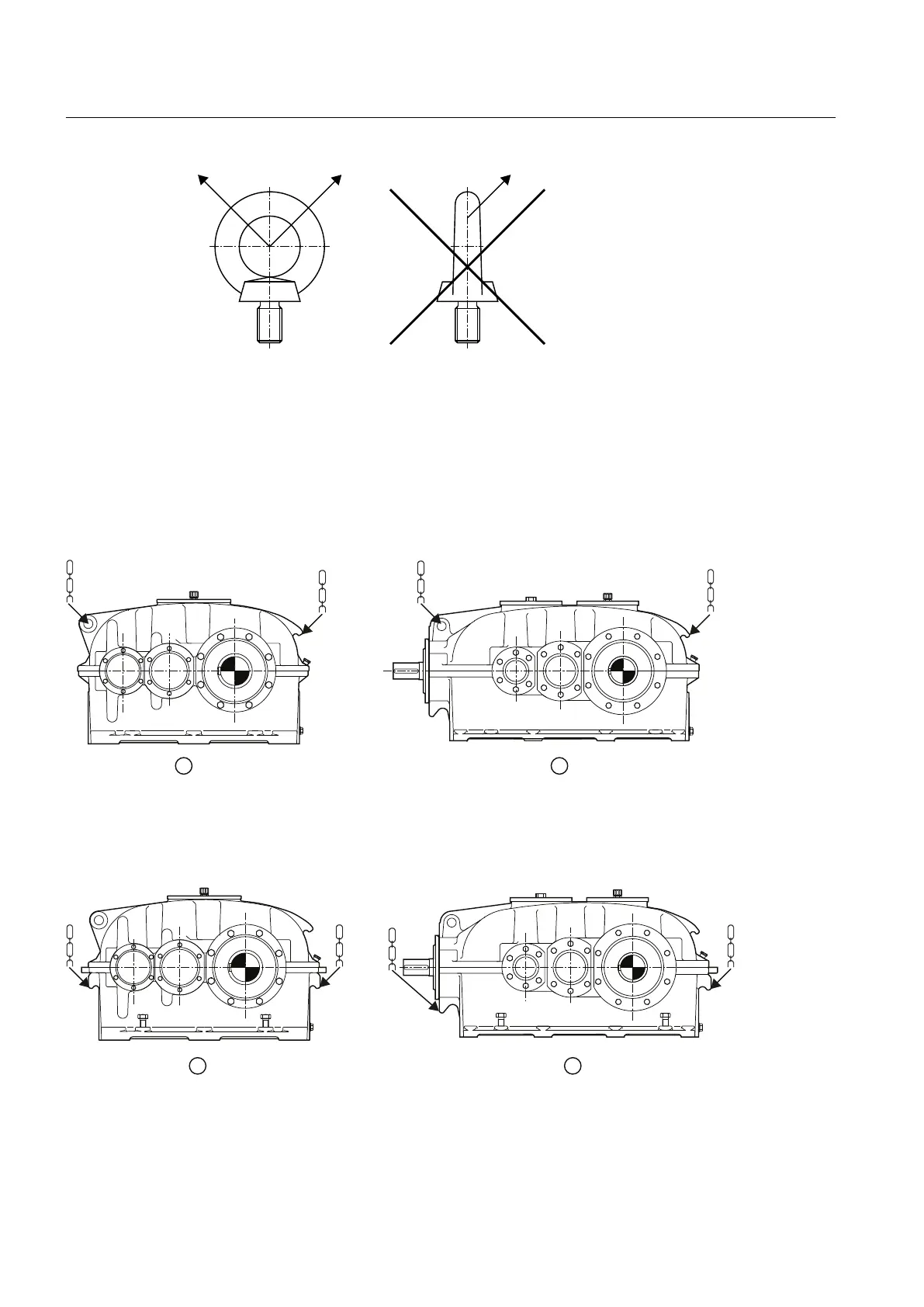
A Permitted shear pulling in direction of eye plane (maximum angle of 45°)
B Non-permitted lateral pulling contrary to direction of eye plane
Figure 4-2 Shear and lateral pulling when using eye bolts
Position of attachment points
The diagram below shows the position of the attachment points on type S.N ≤ 280 and K.N ≤
280 gear units:
① S.N ≤ 280 ② K.N ≤ 280
Figure 4-3 Position of the attachment points, at type S.N ≤ 280 and K.N ≤ 280 gear units
The diagram below shows the position of the attachment points on type S.N ≥ 280 and K.N ≥
280 gear units:
① S.N ≥ 280 ② K.N ≥ 280
Figure 4-4 Position of the attachment points, at type S.N ≥ 280 and K.N ≥ 280 gear units
The diagram below shows the position of the attachment points on a type SZNS gear unit:
Application planning
4.3 Attachment points
REDUREX Gear unit 5200en
48 Operating Instructions 03/2019