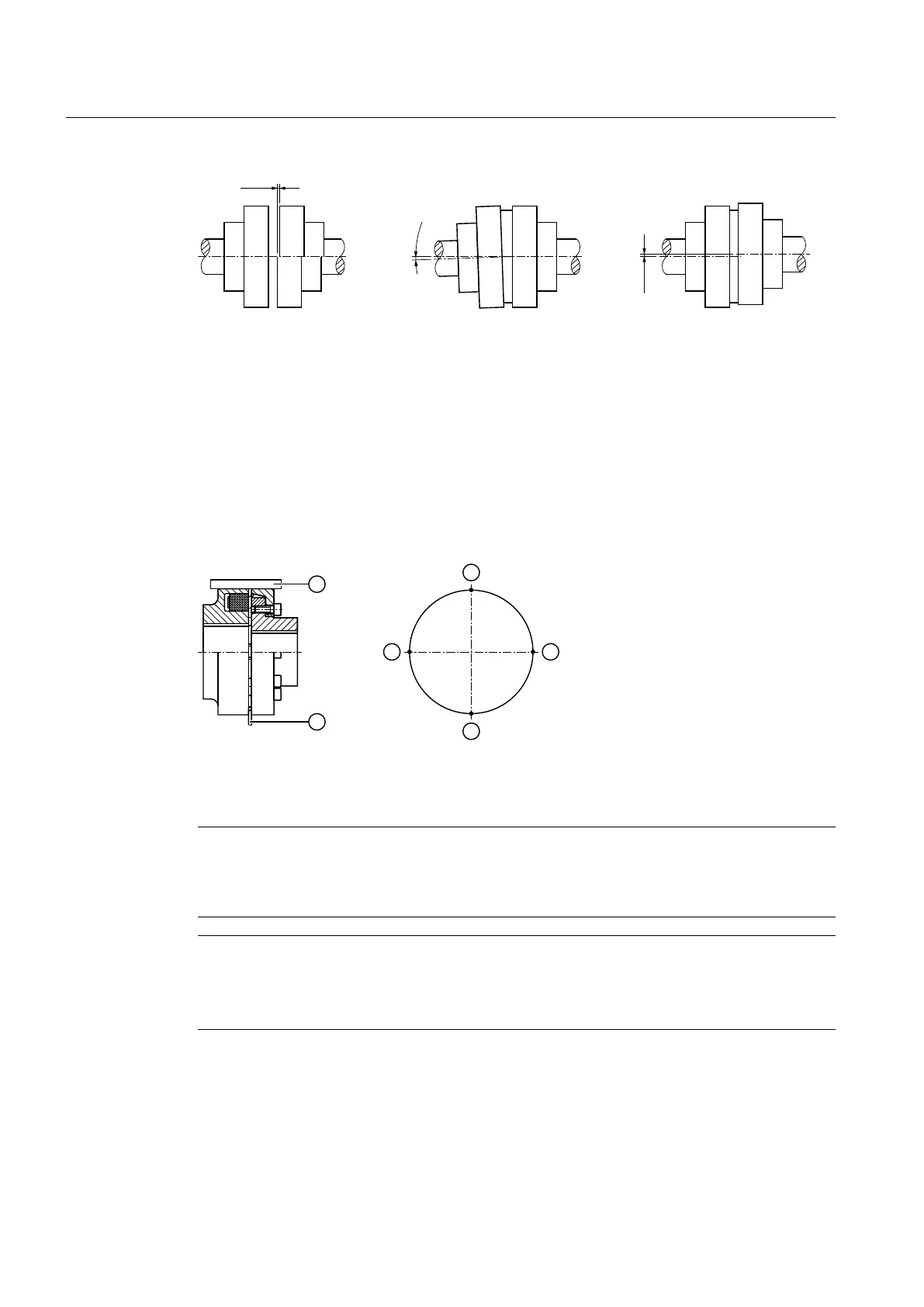
5DGLDOPLVDOLJQPHQW
˂.U
$QJXODUPLVDOLJQPHQW
˂.Z
/DWHUDOPLVDOLJQPHQW
˂.D
˂.D
˂.Z
˂.U
Figure 5-10 Possible displacements
Alignment
Alignment must be carried out in two axis planes that are vertical with respect to one another.
This is possible using rulers (radial offset) and feeler gauges (angular offset) as shown in the
diagram. You will achieve a greater degree of alignment accuracy by using a dial gauge or laser
alignment system.
The diagram below shows the alignment process based on the example of a flexible coupling:
① Ruler ③ Measuring points
② Feeler gauge
Figure 5-11 Alignment process based on the example of a flexible coupling
Note
It is advisable to insert shims or metal sheets under the mounting feet in order to align the drive
components in the vertical direction. It is helpful to use support paws with adjusting screws on
the foundation to adjust the drive components laterally.
Note
Gear unit with motor bell housing
Couplings do not have to be aligned if the gear unit and motor are connected through a motor
bell housing.
Further information
You can find additional information about the permissible alignment errors for Flender
couplings in the complete documentation for the gear unit.
Mounting
5.6 Couplings
REDUREX Gear unit 5200en
72 Operating Instructions 03/2019