8 Installation of FLUXUS ADM 8127B FLUXUS ADM 8027, F801, ADM 8127B
UMFLUXUS_F8V4-6-1EN, 2018-10-10 53
8.6 Connection of the Power Supply
The external protective earth is connected to the equipotential bonding terminal on the housing of the transmitter (see Fig.
8.2).
• Select the cable gland for mines for the connection of the power supply. After the installation, the cable has to fit firmly in
the cable gland for mines:
– M25 (9/12) for cable diameters 9...12 mm
– M25 (14/16) for cable diameters 14...16 mm
• Prepare the power cable with the cable gland for mines.
• Remove as little of the insulation as possible when stripping the cable. The insulation has to cover the lead up to the ter-
minal.
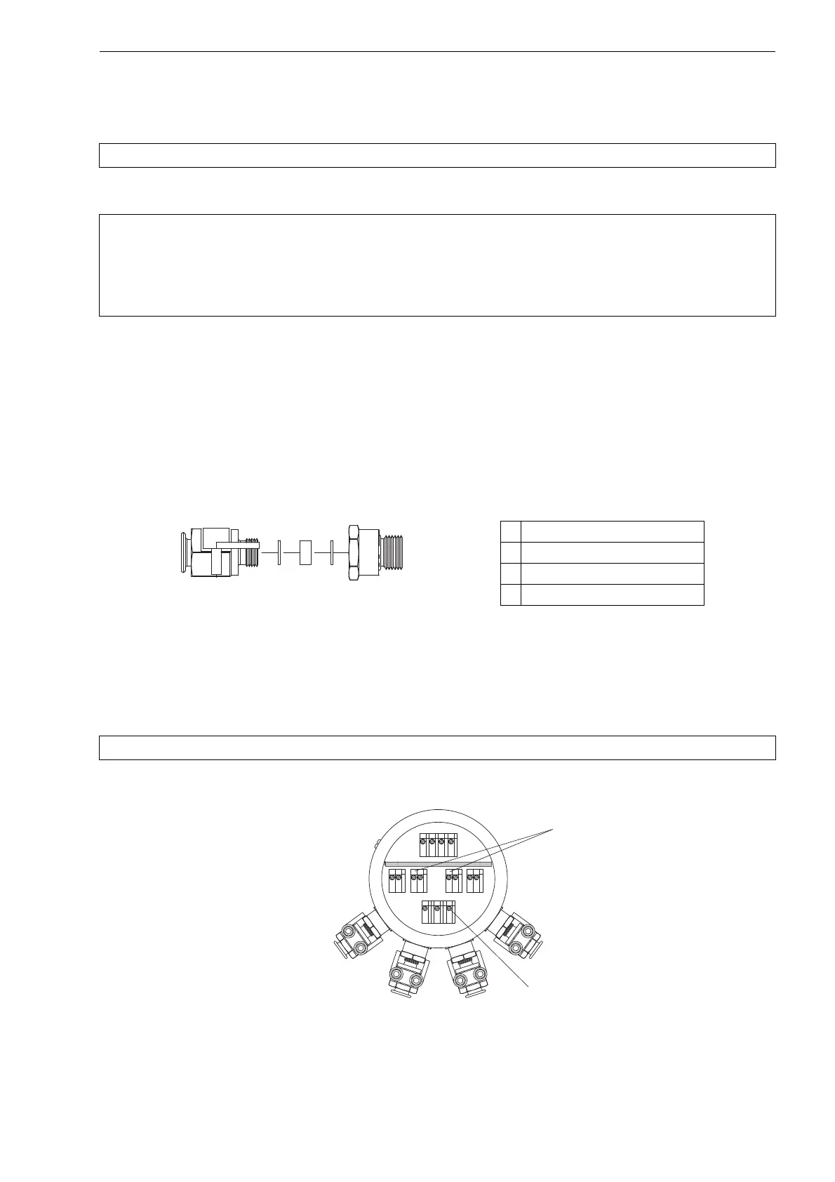
• Push the power cable through the screwed socket (1), the compression rings (2), the sealing ring (3) and the gland body
(4) (see Fig. 8.7).
• Insert the power cable into the housing.
• Screw the gland body (4) into the housing (see Fig. 8.7).
• Fix the screwed socket (2) and the gland body (4) with the clamp by firmly tightening the screws of the clamp.
• Connect the leads to the terminals of the transmitter (see Fig. 8.3, Fig. 8.8 and Tab. 8.2).
Attention! Observe the "Safety Instructions for the Use in Explosive Atmosphere" (see document SIFLUXUS).
Attention! According to IEC 61010-1:2010, a switch has to be provided near the measuring instrument in the
building installation, easily accessible for the user and marked as a disconnection device for the mea-
suring instrument.
If the measuring instrument is used in an explosive atmosphere, the switch should be installed out-
side the explosive atmosphere. If this is not possible, the switch should be installed in the least haz-
ardous area.
Fig. 8.7: Cable gland for mines M25
Attention! Observe the "Safety Instructions for the Use in Explosive Atmosphere" (see document SIFLUXUS).
Fig. 8.8: Terminals for the connection of the power supply and the outputs
1
2
3
4
2
1 screwed socket with clamp
2 compression ring
3 sealing ring
4 gland body
AR
2
Schirm
Schirm
3
13
14
AV
AVS
ARS
PE
L-
L+
 Loading...


