FLUXUS F808, F809 7 Installation of FLUXUS F809
72 UMFLUXUS_F808_8091V1-2-1EN, 2019-08-23
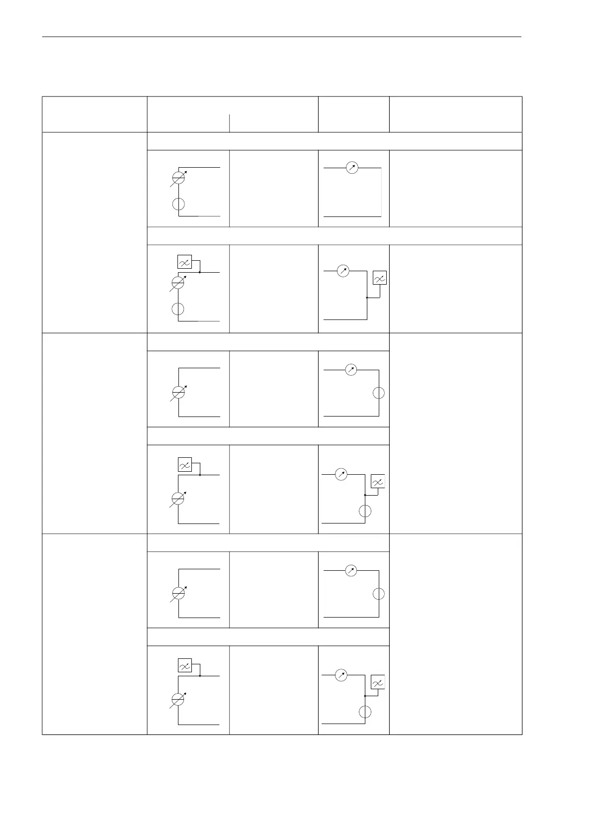
active current loop/HART
F809**-A1
F809**-F1
current loop
I1/I2: 2/4 (+)
I1/I2: 1/3 (-)
R
ext
< 500 Ω
HART mode
I1/I2: 2/4 (+)
I1/I2: 1/3 (-)
U
int
= 24 V
passive current loop/HART
F809**-A1
F809**-F1
current loop U
ext
=
7...30 V
U
ext
> 0.022 A
.
R
ext
[Ω] + 7 V
example:
U
ext
= 12 V
R
ext
≤ 227 Ω
current during transmitter error:
I
fault
= 3.2...3.5 mA
I1/I2: 1/3 (-)
I1/I2: 2/4 (+)
HART mode
I1/I2: 1/3 (-)
I1/I2: 2/4 (+)
intrinsically safe current
loop/HART
F809**-A1A
current loop U
i
= 30 V DC
I
i
= 100 mA
P
i
= 0.75 W
U
ext
≤ U
i
U
ext
> 0.022 A · [Ω] + 7 V
≥ U
ext
/I
i
example:
U
ext
= 24 V
240 Ω ≤ R
ext
≤ 770 Ω
current during transmitter error:
I
fault
= 3.2...3.5 mA
I1/I2: 1 (-)
I1/I2: 2 (+)
HART mode
I1/I2: 1 (-)
I1/I2: 2 (+)
Tab. 7.14: Circuits of the outputs
output transmitter external circuit remark
internal circuit connection
The number, type and connections of the outputs are customized.
R
ext
is the sum of all ohmic resistances in the circuit (e.g. resistance of the conductors, resistance of the amperemeter/voltmeter).
+
-
mA
+
-
U
int
+
-
mA
mA
U
ext
-
+
mA
U
ext
-
+
R
ext
max
R
ext
min
mA
U
ext
-
+
mA
U
ext
-
+
 Loading...


