Chapter 2: Mass Cytometry and CyTOF XT
CyTOF XT System Components Overview
30 CyTOF XT User Guide
Heater Assembly
Overview
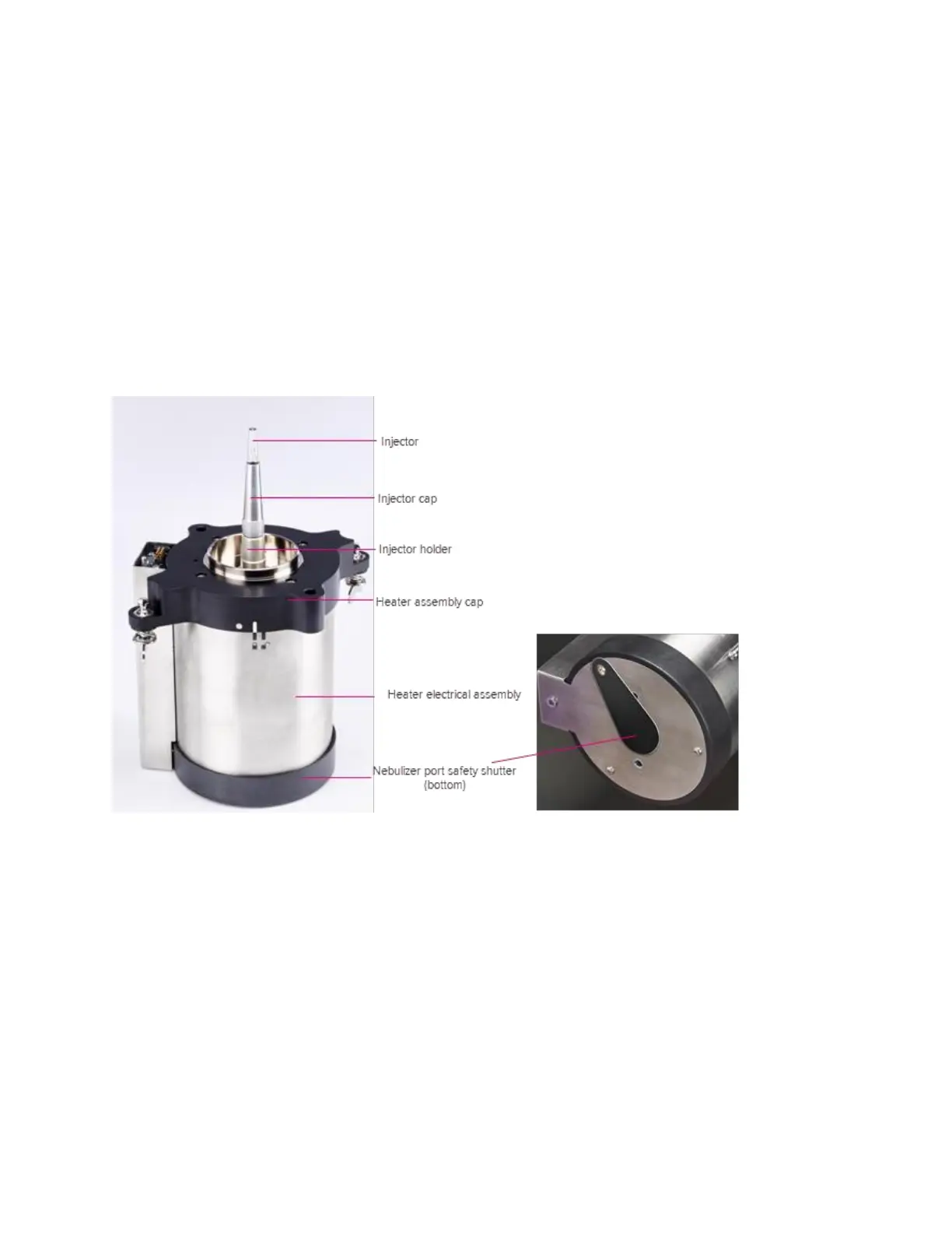
The heater assembly is comprised of a heater unit, the spray chamber, and the injector
holder, secured by the heater assembly cap. The injector is inserted into the injector holder,
which is threaded onto the heater assembly cap. The injector cap is then placed over the
injector and tightened in place. The nebulizer tip is inserted into the nebulizer port on the
front face of the heater assembly.
IMPORTANT Apply gentle downward pressure on the injector so that it remains at its
lowest position while threading the injector cap. The injector must be in the lowest position
to avoid damage during operation.
Figure 20. The heater assembly