vii
List of Figures
Title Page
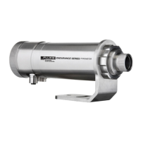
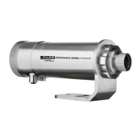
Figure 1: Identification matrix for Endurance with integrated sensor head ................. 4
Figure 2: Spot size calculation regarding the distance to the integrated sensor head
........................................................................................................................... 13
Figure 3: Dimensions of the Endurance Sensor without Air/Water Cooled Housing 14
Figure 4: Proper Sensor Placement in 1-Color Mode .............................................. 16
Figure 5: Sensor Placement in 2-Color Mode .......................................................... 17
Figure 6: Acceptable Sensor Viewing Angles .......................................................... 18
Figure 7: Sensor Eyepiece and Reticle.................................................................... 19
Figure 8: M16 12-Pin connector (upper), the corresponding cable socket (lower), the
cable wire coding table (right)............................................................................. 20
Figure 9: M12 Socket (left) and the corresponding cable plug (right) ....................... 21
Figure 10: Ethernet Cable with M12 Plug and RJ45 Connector ............................... 21
Figure 11: M16 12-Conductor shielded cable with colored wire/signal assignments 22
Figure 12: M12 4-Conductor shielded cable with RJ45 on counter side................... 22
Figure 13: Endurance series labeled terminal block ................................................ 23
Figure 14: USB/RS485 Converter ........................................................................... 24
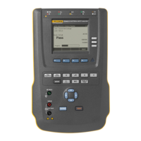
Figure 15: Control Panel ......................................................................................... 25
Figure 16: Upper Object/Target Temperature Display ............................................. 25
Figure 17: Lower Screen / Menu Display ................................................................. 26
Figure 18: Upper LASER / LED /CAMERA Activation LED (red) ............................. 26
Figure 19: Lower Status Indicator LED (green) ........................................................ 26
Figure 20: Overview about the menu structure with five (5) sub-menus .................. 28
Figure 21: The INFORMATION MENU with sensor type related variations ............. 29
Figure 22: The CONFIGURATION MENU with sensor type related variations......... 31
Figure 23: The UNIT SETUP MENU with sensor type related variations ................. 33
Figure 24: The static (fixed) INTERFACE MENU .................................................... 36
Figure 25: The static (fixed) ANALOG MENU .......................................................... 38
Figure 26: Averaging ............................................................................................... 39
Figure 27: Peak Hold reset by Peak Hold Time expiration ....................................... 40
Figure 28: Peak Hold reset by external Trigger signal ............................................. 40
Figure 29: Perpendicular Signal Drop (default mode) .............................................. 41
Figure 30: Linear Signal Drop (decay mode) ........................................................... 41
Figure 31: Average Time Dependent Signal Drop (averaging mode) ....................... 42
Figure 32: Advanced Peak Hold .............................................................................. 42
Figure 33: Valley Hold ............................................................................................. 43
Figure 34: Deadband Example ................................................................................ 44
Figure 35: LASER Spot Size Indication ................................................................... 46
Figure 36: LED Spot Size Indication ........................................................................ 47
Figure 37: Endurance Head with Air/Water-Cooled Housing ................................... 49
Figure 38: Adding modules using Controller Organizer ........................................... 57
Figure 39: Selecting Endurance EDS from the Library ............................................ 57
Figure 40: Device Settings (EDS) ............................................................................ 58
Figure 41: Selecting Generic Ethernet Module from the Library .............................. 58
Figure 42: Device Settings via Manual Configuration .............................................. 59
Figure 43: Endurance Configuration Data as seen in Controller Tags (Rockwell
Studio5000 Software) ......................................................................................... 60
Figure 44: Controller tags: Parameter number and value and their destination
registers in the device ........................................................................................ 61
Figure 45: Sample instruction for sending output data ............................................. 61
Figure 46: Input data conversion ............................................................................. 61
Figure 47: High Temp. Multi-Conductor Cable with M16 Connector (E-2CCBxx) .... 64
Figure 48: Low Temp. Multi-Conductor Cable with M16 Connector (E-2CLTCBxx) . 65