viii
Figure 49: High Temp. Ethernet Cable with M12, RJ45 Connector (E-ETHCBxx) ... 66
Figure 50: Low Temp. Ethernet Cable with M12, RJ45 Connector (E-ETHLTCBxx) 66
Figure 51: Terminal Block (E-TB) with wire color assignment .................................. 67
Figure 52: Terminal Block in a NEMA 4 Enclosure (E-TBN4) .................................. 68
Figure 53: Dimensions of Enclosure ........................................................................ 68
Figure 54: 24VDC, 1.3 A Industrial Power Supply (E-SYSPS) ................................. 69
Figure 55: 24VDC, 1.1A, 100-240VAC power supply in NEMA 4/IP65 case (E-PS) 70
Figure 56: PoE Injector to provides power over a single Ethernet hub (E-POE) ...... 71
Figure 57: 12-socket DIN Cable connector (E-2CCON) for multi-conductor cable ... 72
Figure 58: Modline5 patch cable kit to use existing Modline5 cables (E-M5PK) ....... 72
Figure 59: USB to RS232/422/485 converter (E-USB485)....................................... 73
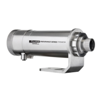
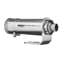
Figure 60: Endurance sensor with Accessories ....................................................... 74
Figure 61: Air purge collar (E-AP) ............................................................................ 75
Figure 62: Pipe adapter to attach sighting tubes (E-PA) .......................................... 75
Figure 63: Mounting nut (E-MN) .............................................................................. 76
Figure 64: Drawing and Photo of Fixed Bracket (E-FB) ........................................... 76
Figure 65: Adjustable bracket (E-AB) ...................................................................... 77
Figure 66: Swivel bracket (E-SB)............................................................................. 77
Figure 67: Right angle mirror for targets at right angles to sensor axis (E-RA) ........ 78
Figure 68: Adapter kit to use Endurance sensors in Modline5 WJA (E-M5WJAK) ... 78
Figure 69: Endurance universal adapter accessory (E-UAA) ................................... 79
Figure 70: Adapter kit for Endurance in WJ-5 water jacket installations (E-AK-7) .... 79
Figure 71: Mounting flange (E-MF-7) ....................................................................... 80
Figure 72: Flange adapter to allow Endurance to mount to MF-7 (E-MFA-7) ........... 80
Figure 73: Replacement glass end-cap for Endurance sensors (E-ECAP) .............. 81
Figure 74: Protective front window, including O-Ring (E-PW) .................................. 81
Figure 75: Polarizing filter end cap for use in high temperature applic. (E-PFEC) .... 82
Figure 76: Model E1RL Percentage of Allowed Signal Reduction............................ 96
Figure 77: Model E1RH Percentage of Allowed Signal Reduction ........................... 96
Figure 78: Model E2RL Percentage of Allowed Signal Reduction............................ 97